Eaton Fuller Hybrid Transmission Kodi Fault 58 – Output Shaft Speed Sensor
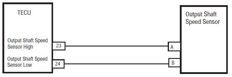
Faji Kodi për Eaton Hybrid Sistemet Drive modele (MY08) EH-8E306A-U, EH-8E306A-UPG, EH-8E306A-UP, EH-8E306A-CD, EH-8E306A-T, EH-6E606B-CD, (MY09) EH-8E406A-U / P, EH-8E406A-UP, EH-8E406A-UPG, EH-8E406A-CD, EH-8E406A-CDG, EH-8E406A-CDR, EH-8E406A-T, EH-6E706B-CD, EH-6E706B-P dhe EH-6E706B-UPG. Lexoni më poshtë për të mësuar se si të provoni, të qartë dhe të rregulluar gabimet kodin faji për Freightliner tuaj, Mack, Peterbilt, Kenworth, Volvo, ndërkombëtar, dhe kamion të rëndë dhe pajisjet. Output Shaft Speed Sensor është e vendosur në kopertinën e pasme mbajtur më së 12 Pozicioni ora. Sensori është një kamionçinë magnetike që prodhon një tension AC si lëviz dhëmbëve rrota tone të fundit në fund të sensor. në boshe, prodhimi Speed Sensor është i ulët dhe kjo rrit si shpejtësia e rritet bosht prodhimit.
faj Kodin 58 – Output Zbulimi Shaft Speed Sensor
Parakushtet e mëposhtme duhet të plotësohen para se sistemi zbulon defektin:
- Electronic Control Unit transmetimit (TECU) tension ndezjen është më i madh se 7 volt dhe më pak se 16 volt.
- FMN 2 nuk vendos nëse nuk është tashmë një FMI aktiv 5 për Input Output ose Heshta Speed Sensore.
shënim: Kur troubleshooting një kod joaktive referohen të Produkt Diagnostic Mode (PDM)
Kushtet për Set Kodi Fault Active
- FMN 2 është vendosur kur shpejtësia bosht prodhimit TECU krahasohet me shpejtësinë me bosht input dhe ajo prodhon një lexim kundërshtim për 1 dytë ose me i madh.
- FMN 3, 4 janë të vendosur kur TECU zbulon një të shkurtër në tokë, të shkurtër të baterisë, ose shpejtësia bosht prodhimit është 0 për 1 dytë ose me i madh.
- FMN 5 është vendosur kur TECU zbulon një qark të hapur dhe prodhimi Shaft Speed Sensor është 0 për 1 dytë ose me i madh.
Fallback Kur Code Fault 58 është vendosur ndodhin kushtet e mëposhtme:
- Red "shërbim" ndriçues të lehta dhe një "F" pulson në ekran veshje.
- Faji është i ruajtur në kujtesën TECU.
- mode operacion ndryshon në mënyrë "AutoShift fallback".
- Nëse kjo faji ndodh ndërsa lëviz, transmetimi mbetet në marshin aktual dhe tufë hap kur ndalon automjeti.
Kushtet për Set Fault Code joaktiv
Vetëm gabime jo aktive mund të pastrohen nga Njësia e kontrollit elektronik të Transmisionit (TECU) ose historia HCM përdorur ServiceRanger. TECU automatikisht pastron gabimet nga historia pas 200 orë dhe HCM automatikisht pastron gabimet nga historia pas faj ka qenë inaktive për 200 orë.
Ky kod faji mund të shkaktohet nga ndonjë nga këto:
- FMN 2
- Output Shaft Speed Sensor
- TECU
- transmetimit Shaloni
- Dëmtuar përgatitet Transmisionit
- Ndotja në Output Shaft Speed sensor
- FMN 3, 4, 5
- Output Shaft Speed Sensor
- TECU
- transmetimit Shaloni
faj Kodin 58 – Output Test Shaft Speed Sensor
Identifikimi Komponenti:
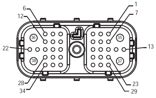
Shaloni Front View
(TECU – Sistemi Interface Connector)
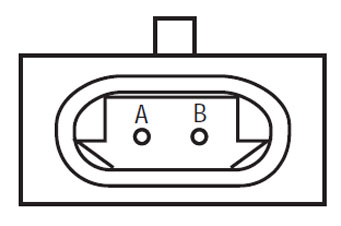
Output Shaft Speed Sensor
SHËNIM: Referojuni Eaton Komponenti Hybrid dhe Connector Vendndodhja për Locations lidhës në MY08 Systems
SHËNIM: Referojuni Eaton Komponenti Hybrid dhe Connector Vendndodhja për Locations lidhës në MY09 Systems.
Paralajmërimet & keshillon
rrezik: Rreziku tregon se do të plagoseni rëndë ose do të vriteni nëse nuk ndiqni procedurën e treguar.
paralajmërim: Warning tregon një rrezik të menjëhershëm, i cili mund të rezultojë në dëmtim të rëndë personal nëse nuk ndiqni procedurën e treguar.
Kujdes: Kujdes tregon që dëmtimi i automjetit ose pronës mund të ndodhë nëse nuk ndiqni procedurën e treguar.
shënim: Shënimi tregon detaje shtesë që do të ndihmojnë në diagnostikimin ose riparimin e një përbërësi / sistemi.
Ndjekin procedurat e përcaktuara në urdhrin e treguar për të shmangur dëmtimin personal:
1. Nëse kone e tensionit të lartë janë rreth automjetit dhe lokaut është i instaluar në PEC, i vetmi person që duhet të lejohet të fillojë të automjetit është personi që ka nënshkruar tag lokaut.
2. Para se të punuar në një automjet ose duke e lënë taksi, ndërsa motori është i rrjedhshëm, ju duhet të vendosni levë ndryshim në "N" të vendosur frenave parkimi, dhe bllokojnë rrotat.
3. Për arsye sigurie, gjithmonë të angazhuar frenat e shërbimit para se të zgjedhur pozicionet veshje nga "N."
4. Para fillimit të një automjeti gjithmonë të ulur në vendin e shoferit, zgjidhni "N" Për kontrollin shift, dhe të vendosur frenat e parkimit.
5. Në automjetet me ePTO, motor dhe / ose
Motor / Generator mund të fillojë në mënyrë të ePTO. Asnjëherë mos kryer ndonjë mirëmbajtjen ose punojnë në automjet, ndërsa në këtë mënyrë.
6. 12-Volt Battery pozitiv (+) dhe negative (-) duhet të jenë të shkyçur para çdo saldim në çdo makinë hibride pajisur.
Kujdes: Ndjekin procedurat e përcaktuara në urdhrin e treguar për të shmangur pajisjet keqfunksionim ose dëmtim.
Kujdes: Mos e lëshoni frenin e parkimit ose mos u përpiqni të zgjidhni një ingranazh derisa presioni i ajrit të jetë në nivelin e duhur.
Kujdes: Për të shmangur dëmtimin e transmisionit gjatë tërheqjes vendosni levën e ndërrimit në "N" dhe ngrini rrotat e makinës nga toka ose shkëputni vijën e makinës.
Paralajmërimet me tension të lartë & keshillon
- Përdorni CO2 apo të thatë kimike aparatet zjarr.
- Instalime elektrike të tensionit të lartë është e mbuluar në izolim portokalli ose tub ndërlikuar dhe të shënuara me etiketat paralajmërim në lidhje.
- Të gjitha Eaton® Hybrid Diesel / automjeteve elektrike do të shënohet "Hybrid’ në pjesën e jashtme të automjetit, së bashku me etiketën ndryshim në dash.
- Referojuni OEM për vend të veçantë e shasi montuar komponentëve hibride.
- A nuk e prerë në kabllot të tensionit të lartë portokalli.
- A nuk e prerë në ose hapni Pejës.
- A nuk e prerë në ose hapni Converter DC / DC.
- A nuk e prerë në ose të hapur inverter.
Një zonë tampon duhet të jenë të ngritur dhe të lartë të tensionit të izoluar doreza gome (klasë 0 me mbrojtës të lëkurës) janë të nevojshme para se të punojnë në tension të lartë. Dështimi për të ndjekur këto udhëzime mund të rezultojë në lëndime të rënda personale ose vdekje.
Të dorashka gome-izoluar që duhet të vishen duke punuar në sistemin e tensionit të lartë janë të klasit 0 me mbrojtës të lëkurës. Doreza gome duhet të testohet para çdo përdorimi pas procedurës gome doreza izoluese testimit gjendet në "Mjetet diagnostike / Publikime të Shërbimit" në faqen 6. Dështimi për të ndjekur këto udhëzime mund të rezultojë në lëndime të rënda personale ose vdekje.
Para inspektimin apo duke punuar në ndonjë kabllo të tensionit të lartë apo komponentëve të "High-Voltage Shërbimi Shutdown dhe Power-Up procedurës" në faqen 4 duhet të ndiqet. Dështimi për të ndjekur këto udhëzime mund të rezultojë në lëndime të rënda personale ose vdekje.
Pajisjet lokaut dhe Tagout duhet të hiqet vetëm nga tekniku që vendosen pajisjet Lokaut dhe Tagout në automjet. Dështimi për të ndjekur këto udhëzime mund të rezultojë në lëndime të rënda personale ose vdekje.
gome izoluar doreza të tensionit të lartë (klasë 0 me mbrojtës të lëkurës) duhet të jetë i veshur kur punojnë në ndonjë
kabllo të tensionit të lartë. E "High-Voltage Shërbimi Shutdown dhe Power-Up Procedura" në faqen 4 duhet të ndiqen para se të hequr ndonjë kabllo të tensionit të lartë. Dështimi për të ndjekur këto udhëzime mund të rezultojë në lëndime të rënda personale ose vdekje.
kabllo të tensionit të lartë dhe instalime elektrike janë portokalli dhe të përmbajë një etiketë paralajmëruese në lidhje. komponentëve të tensionit të lartë janë të shënuara me një etiketë. gome izoluar doreza të tensionit të lartë (klasë 0 me mbrojtës të lëkurës) duhet të përdoret kur punojnë në ndonjë nga këto komponente. Dështimi për të ndjekur këto udhëzime mund të rezultojë në lëndime të rënda personale ose vdekje.
Me tension të lartë Procedurat Shutdown Shërbimi
 1. Follow "High-Voltage Work Area" Procedura.
2. Gjeni kuqe PEC Shërbimit të kaluar në pjesën e përparme të Pejës dhe të shtyjë kaloni off.
3. Hiqni kapakun Shërbimi Switch dhe instaloni Bracket lokaut (J48506).
4. tag kapem për lokaut Bracket.
5. Siguruar Switch PEC Shërbimit nuk mund të lëvizin nga pozicioni off.
6. Lejo sistemi për të vendosur për një minimum prej 5 minuta për shkarkimin tension të lartë.
7. Lidhu ServiceRanger dhe të parë të dhënat Monitor PID 116 quajtur "Potenciali High-Voltage Battery." Përdorimi SPN 520323 për lidhje J1939 "Battery Voltage RB" (Relay Box).
8. Tensioni duhet të jetë 30 volt ose më pak. Në qoftë se tensioni është më lart 30 volt, nuk punojnë në automjet dhe të kontaktoni Eaton® në 1-800-826-HELP (4357).
9. Kthehet kyç ndezjen off dhe të vazhdojë për të riparuar ose hap troubleshooting.
shënim: Tensioni bie në zero, kur çelësi është jashtë.
Procedura High-Voltage Shërbimi Power-Up
1. Instalo të gjitha lidhje të tensionit të lartë në pozicionet e tyre të mbyllura.
2. Nëse ju jeni personi punon në automjet, hiqni lokaut Bracket dhe tag.
3. Reinstall lokaut Bracket mbi Shërbimit Switch.
4. Pull Shërbimin Kaloni jashtë dhe le të vendosur automjetit për 2 minuta.
5. Filloni automjetit kur është e përshtatshme.
Eaton Komponenti Hybrid dhe Connector Vendndodhja

Eaton Komponenti Hybrid dhe Connector Vendndodhja MY09 Systems

HAPI 1. Verifikoni vazhdimësinë e qarqeve sensor Transmission Shaloni.
- Retrieve kodet aktive faj dhe SIMF me ServiceRanger përdorimin e 9-Way diagnostike Connector.
- off Key.
- kabllo Disconnect negative bateri.
- Shkëputni parzmoren e transmisionit 38- Way Connector.
- Masa rezistencë midis transmetimin Shaloni 38-Way lidhës pin 23 dhe Pin 24 dhe Pin 23 dhe terren:
- Në qoftë se rezistenca është ohms 2K-4.5K dhe Pin 23 në tokë është 10k ohms ose më e madhe, shkoni në hapin 2.
- Në qoftë se rezistenca është jashtë gamës, shkoni në hapin 4.
HAPI 2. Verifikoni tensionit të qarqeve sensor Transmission shfrytëzuar në tokë.
- Key në.
- tension Masa midis Transmission Shaloni 38-Way lidhës pin 23 dhe terren.
- Nëse tensioni është 0 volt, shkoni në hapin 3.
- Në qoftë se tensioni është 11-13 volt, riparimin e shkurtër të baterisë në parzmore automjeteve, pastaj të shkojnë në hapin 6.
HAPI 3. Verifikuar integritetin e prodhimit Heshta Speed sensor.
- Inspect Output Heshta Speed Sensor për ndotje ose dëmtim.
- Në qoftë se nuk ka problem gjetur, zëvendësojë Electronic Control Unit Transmission (TECU) (vetëm nëse kodi faji është Aktiv), pastaj të shkojnë në hapin 6.
- Nëse problemi është gjetur ose janë dërguar këtu nga hapi 4 ose 5, zëvendësojë Output Heshta Speed sensor dhe të inspektojë Wheel tonin për dëmin, diarre apo korrozioni. Shko tek Hapi 6.
HAPI 4. Verifikoni vazhdimësinë e prodhimit Heshta Speed sensor.
- Shkëputje Shaloni Transmisionit nga Output Shaft Speed sensor.
- Measure resistance between Output Shaft Speed Sensor Pin A and Pin B:
- Në qoftë se rezistenca është 2K-4.5K ohms, shkoni në hapin 5.
- Në qoftë se rezistenca është jashtë varg, shkoni në hapin 3.
HAPI 5. Verifikoni vazhdimësinë e prodhimit Heshta shpejtësi sensor dhe toka.
- Masa rezistencë midis Output Heshta Speed sensor Pin A dhe toka:
- Në qoftë se rezistenca është 10K ohms ose më e madhe, zëvendësojë Shaloni Transmisionit, pastaj të shkojnë në hapin 6.
- Në qoftë se rezistenca është më pak se 10K ohms, shkoni në hapin 3.
HAPI 6. Verifikoni riparim.
- off Key.
- Reconnect gjitha lidhësit dhe kabllo negative e baterisë.
- Verifikoni instalimin e duhur të sensor shpejtësi.
- Key në.
- Kodet e qarta, Shiko Gabimet qarta Inactive.
- Drive automjetin dhe përpjekje për të rivendosur kodin.
- Kontrollo për kodet, Shiko Shiko gabimet aktive dhe jo aktive.
- Nëse jo kodet, Testi është i plotë.
- Nëse Code faji 58 duket, gjetur gabim në testim, shkoni në hapin 1.
- Nëse një kod tjetër përveç 58 duket, Shiko Faji Lista Code Indeksi.
ndonjë pjesa e transmetimit ju keni nevojë për ne kemi atë! Të njëjtën ditë të anijeve në dispozicion, botëror.
DUHET pa mbështetje nga një prej ekspertëve tanë?