[fusion_builder_container hundred_percent=nohundred_percent_height=nohundred_percent_height_scroll=nohundred_percent_height_center_content=yesequal_height_columns=nomenu_anchor=”” hide_on_mobile=small-visibility,medium-visibility,large-visibilitystatus=publishedpublish_date=”” class=”” id=”” background_color=”” background_image=”” background_position=center centerbackground_repeat=no-repeatfade=nobackground_parallax=noneenable_mobile=noparallax_speed=”0.3″ video_mp4=”” video_webm=”” video_ogv=”” video_url=”” video_aspect_ratio=”16:9″ video_loop=yesvideo_mute=yesvideo_preview_image=”” border_size=”” border_color=”” border_style=solidmargin_top=”35″ margin_bottom=”” padding_top=”” padding_right=”” padding_bottom=”” padding_left=””][fusion_builder_row][fusion_builder_column type=”1_1layout=”1_1spacing=”” center_content=nolink=”” target=_selfmin_height=”” hide_on_mobile=small-visibility,medium-visibility,large-visibilityclass=”” id=”” background_color=”” background_image=”” background_image_id=”” background_position=left topbackground_repeat=no-repeathover_type=noneborder_size=”0″ border_color=”” border_style=solidborder_position=allpadding_top=”” padding_right=”” padding_bottom=”” padding_left=”” margin_top=”” margin_bottom=”” animation_type=”” animation_direction=leftanimation_speed=”0.3″ animation_offset=”” last=no”][fusion_text columns=”” column_min_width=”” column_spacing=”” rule_style=defaultrule_size=”” rule_color=”” hide_on_mobile=small-visibility,medium-visibility,large-visibilityclass=”” id=””]

Eaton Fuller Hybridgetriebe Fehlercode 116 – Hochspannungsrelais -(MY08-Systeme)

[/fusion_text][/fusion_builder_column][/fusion_builder_row][/fusion_builder_container][fusion_builder_container hundred_percent=nohundred_percent_height=nohundred_percent_height_scroll=nohundred_percent_height_center_content=yesequal_height_columns=nomenu_anchor=”” hide_on_mobile=small-visibility,medium-visibility,large-visibilitystatus=publishedpublish_date=”” class=”” id=”” background_color=”” background_image=”” background_position=center centerbackground_repeat=no-repeatfade=nobackground_parallax=noneenable_mobile=noparallax_speed=”0.3″ video_mp4=”” video_webm=”” video_ogv=”” video_url=”” video_aspect_ratio=”16:9″ video_loop=yesvideo_mute=yesvideo_preview_image=”” border_size=”” border_color=”” border_style=solidmargin_top=”” margin_bottom=”” padding_top=”” padding_right=”” padding_bottom=”” padding_left=””][fusion_builder_row][fusion_builder_column type=”1_1layout=”1_1spacing=”” center_content=nolink=”” target=_selfmin_height=”” hide_on_mobile=small-visibility,medium-visibility,large-visibilityclass=”” id=”” background_color=”” background_image=”” background_image_id=”” background_position=left topbackground_repeat=no-repeathover_type=noneborder_size=”0″ border_color=”” border_style=solidborder_position=allpadding_top=”” padding_right=”” padding_bottom=”” padding_left=”” margin_top=”” margin_bottom=”” animation_type=”” animation_direction=leftanimation_speed=”0.3″ animation_offset=”” last=no”][fusion_text columns=”” column_min_width=”” column_spacing=”” rule_style=defaultrule_size=”” rule_color=”” hide_on_mobile=small-visibility,medium-visibility,large-visibilityclass=”” id=””]

Fehlercode für Eaton Hybrid Drive System Modelle (MY08) EH-U-8E306A, EH-8E306A-UPG, EH-8E306A-UP, EH-8E306A-CD, EH-8E306A-T, EH-6E606B-CD. Lesen Sie unten, um zu erfahren wie zu testen, löschen und Fehlercode Fehler für Ihre Freight beheben, Mack, Peterbilt, Kenworth, Volvo, International, schwere und schwere Lkw und Ausrüstung. The High-Voltage Relays are located inside the Power Electronics Carrier (PEC) in der Relais-Box-Einheit. There is 1 precharge relay on the positive side, ein zusätzliches Relais auf der positiven, und 1 on the negative for a total of 3. Diese Relais sind in der Regel offen, wenn das System ausgeschaltet ist. Die Relais werden durch den Frequenzumrichter gesteuert.

Falscher Code 116 – High Voltage Relays Detection

Folgende Voraussetzungen müssen erfüllt sein, bevor das System den Fehler erkennt:

  • Inverter-Zündspannung größer ist als 7 Volt und weniger als 16 Volt.

Hinweis: Wenn Sie eine inaktive Code zur Fehlerbehebung finden Sie in der Produktdiagnosemodus (PDM)

Bedingungen setzen Fehlercode Aktiv

  • IWF 10 is set when the Inverter detects the input voltage measured at the capacitor is less than 210 volts within 3 seconds after the sub-relay closed in the Relay Box.
  • IWF 14 is set when only the negative relay in the Relay Box is on and capacitor voltage decreases less than 10 volts/5 seconds when initial capacitor voltage was greater than 200 volts and motor speed less than 500 min-1, or there is a detect error in the initial check.

Notlösung, wenn Fehlercode 116 die folgenden Bedingungen auftreten, eingestellt ist:

  • Bernstein „prüfen Hybrid“ Licht blinkt immer für FMI 10 and remains solid for FMI 14.
  • Der Fehler wird im HCM-Speicher gespeichert.
  • Inverter schaltet Hochspannungsnetz ab.
  • HCM weiterhin das Hybridfahrzeug in einem Modus nur mit Diesel zu steuern,.
  • Getriebe Standardwerte starten Gang 1..

[/fusion_text][fusion_text columns=”” column_min_width=”” column_spacing=”” rule_style=defaultrule_size=”” rule_color=”” hide_on_mobile=small-visibility,medium-visibility,large-visibilityclass=”” id=””]

Bedingungen einzustellen Fehlercode Inaktive

Nur inaktive Fehler können von der Transmission Electronic Control Unit gelöscht werden (TECU) oder HCM Geschichte mit Serviceranger. Die TECU löscht automatisch die Fehler aus der Geschichte nach dem 200 Stunden und die HCM löscht automatisch die Fehler aus der Geschichte nach dem Fehler waren inaktiv für 200 Std.

Dieser Fehlercode kann durch eine der folgenden Bedingungen verursacht werden:

  • IWF 10
    • PEC
    • APG
    • Wandler
    • DC high-voltage cable
    • DC cable interlock loops
    • Trägheitsschalter
    • Service Switch
  • IWF 14
    • Wandler
    • PEC

[/fusion_text][/fusion_builder_column][/fusion_builder_row][/fusion_builder_container][fusion_builder_container hundred_percent=nohundred_percent_height=nohundred_percent_height_scroll=nohundred_percent_height_center_content=yesequal_height_columns=nomenu_anchor=”” hide_on_mobile=small-visibility,medium-visibility,large-visibilitystatus=publishedpublish_date=”” class=”” id=”” background_color=”” background_image=”” background_position=center centerbackground_repeat=no-repeatfade=nobackground_parallax=noneenable_mobile=noparallax_speed=”0.3″ video_mp4=”” video_webm=”” video_ogv=”” video_url=”” video_aspect_ratio=”16:9″ video_loop=yesvideo_mute=yesvideo_preview_image=”” border_size=”” border_color=”” border_style=solidmargin_top=”” margin_bottom=”” padding_top=”” padding_right=”” padding_bottom=”” padding_left=””][fusion_builder_row][fusion_builder_column type=”1_1layout=”1_1spacing=”” center_content=nolink=”” target=_selfmin_height=”” hide_on_mobile=small-visibility,medium-visibility,large-visibilityclass=”” id=”” background_color=”” background_image=”” background_image_id=”” background_position=left topbackground_repeat=no-repeathover_type=noneborder_size=”0″ border_color=”” border_style=solidborder_position=allpadding_top=”” padding_right=”” padding_bottom=”” padding_left=”” margin_top=”” margin_bottom=”” animation_type=”” animation_direction=leftanimation_speed=”0.3″ animation_offset=”” last=no”][fusion_text columns=”” column_min_width=”” column_spacing=”” rule_style=defaultrule_size=”” rule_color=”” hide_on_mobile=small-visibility,medium-visibility,large-visibilityclass=”” id=””]

Falscher Code 116 – High Voltage Relays Test

[/fusion_text][/fusion_builder_column][/fusion_builder_row][/fusion_builder_container][fusion_builder_container hundred_percent=nohundred_percent_height=nohundred_percent_height_scroll=nohundred_percent_height_center_content=yesequal_height_columns=nomenu_anchor=”” hide_on_mobile=small-visibility,medium-visibility,large-visibilitystatus=publishedpublish_date=”” class=”” id=”” background_color=”” background_image=”” background_position=center centerbackground_repeat=no-repeatfade=nobackground_parallax=noneenable_mobile=noparallax_speed=”0.3″ video_mp4=”” video_webm=”” video_ogv=”” video_url=”” video_aspect_ratio=”16:9″ video_loop=yesvideo_mute=yesvideo_preview_image=”” border_size=”” border_color=”” border_style=solidmargin_top=”” margin_bottom=”” padding_top=”” padding_right=”” padding_bottom=”” padding_left=””][fusion_builder_row][fusion_builder_column type=”1_1layout=”1_1spacing=”” center_content=nolink=”” target=_selfmin_height=”” hide_on_mobile=small-visibility,medium-visibility,large-visibilityclass=”” id=”” background_color=”” background_image=”” background_image_id=”” background_position=left topbackground_repeat=no-repeathover_type=noneborder_size=”0″ border_color=”” border_style=solidborder_position=allpadding_top=”” padding_right=”” padding_bottom=”” padding_left=”” margin_top=”” margin_bottom=”” animation_type=”” animation_direction=leftanimation_speed=”0.3″ animation_offset=”” last=no”][fusion_text columns=”” column_min_width=”” column_spacing=”” rule_style=defaultrule_size=”” rule_color=”” hide_on_mobile=small-visibility,medium-visibility,large-visibilityclass=”” id=””]

Identifizierung der Komponenten MY08-Systeme:
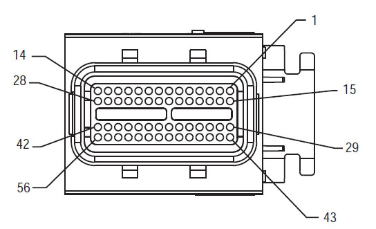
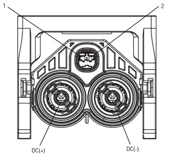
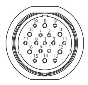
[/fusion_text][/fusion_builder_column][/fusion_builder_row][/fusion_builder_container][fusion_builder_container hundred_percent=yeshundred_percent_height=nohundred_percent_height_scroll=nohundred_percent_height_center_content=yesequal_height_columns=nomenu_anchor=”” hide_on_mobile=small-visibility,medium-visibility,large-visibilitystatus=publishedpublish_date=”” class=”” id=”” background_color=”” background_image=”” background_position=center centerbackground_repeat=no-repeatfade=nobackground_parallax=noneenable_mobile=noparallax_speed=”0.3″ video_mp4=”” video_webm=”” video_ogv=”” video_url=”” video_aspect_ratio=”16:9″ video_loop=yesvideo_mute=yesvideo_preview_image=”” border_size=”” border_color=”” border_style=solidmargin_top=”” margin_bottom=”” padding_top=”” padding_right=”10%” padding_bottom=”” padding_left=”10%”][fusion_builder_row][fusion_builder_column type=”1_3layout=”1_3spacing=”” center_content=nolink=”” target=_selfmin_height=”” hide_on_mobile=small-visibility,medium-visibility,large-visibilityclass=”” id=”” background_color=”” background_image=”” background_image_id=”” background_position=left topbackground_repeat=no-repeathover_type=noneborder_size=”0″ border_color=”” border_style=solidborder_position=allpadding_top=”” padding_right=”” padding_bottom=”” padding_left=”” margin_top=”” margin_bottom=”” animation_type=”” animation_direction=leftanimation_speed=”0.3″ animation_offset=”” last=no”][fusion_imageframe image_id=”14474|fullmax_width=”” style_type=”” blur=”” stylecolor=”” hover_type=nonebordersize=”” bordercolor=”” borderradius=”” align=centerlightbox=nogallery_id=”” lightbox_image=”” lightbox_image_id=”” alt=”Delphi 56-Wege-Gegenstecker Ansicht” link=”” linktarget=_selfhide_on_mobile=small-visibility,medium-visibility,large-visibilityclass=”” id=”” animation_type=”” animation_direction=leftanimation_speed=”0.3″ animation_offset=””]https://www.globaltransmissionsupply.com/wp-content/uploads/Inverter-56-Way-Mating-Connector-View.jpg[/fusion_imageframe][fusion_text columns=”” column_min_width=”” column_spacing=”” rule_style=defaultrule_size=”” rule_color=”” hide_on_mobile=small-visibility,medium-visibility,large-visibilityclass=”” id=””]

56-Way Gegenstecker Ansicht

[/fusion_text][/fusion_builder_column][fusion_builder_column type=”1_3layout=”1_3spacing=”” center_content=nolink=”” target=_selfmin_height=”” hide_on_mobile=small-visibility,medium-visibility,large-visibilityclass=”” id=”” background_color=”” background_image=”” background_image_id=”” background_position=left topbackground_repeat=no-repeathover_type=noneborder_size=”0″ border_color=”” border_style=solidborder_position=allpadding_top=”” padding_right=”” padding_bottom=”” padding_left=”” margin_top=”” margin_bottom=”” animation_type=”” animation_direction=leftanimation_speed=”0.3″ animation_offset=”” last=no”][fusion_imageframe image_id=”14635|fullmax_width=”” style_type=”” blur=”” stylecolor=”” hover_type=nonebordersize=”” bordercolor=”” borderradius=”” align=centerlightbox=nogallery_id=”” lightbox_image=”” lightbox_image_id=”” alt=”Hochspannungs-DC-Anschluss Ansicht Yazaki-Anschluss” link=”” linktarget=_selfhide_on_mobile=small-visibility,medium-visibility,large-visibilityclass=”” id=”” animation_type=”” animation_direction=leftanimation_speed=”0.3″ animation_offset=””]https://www.globaltransmissionsupply.com/wp-content/uploads/High-Voltage-DC-Connector-View.jpg[/fusion_imageframe][fusion_text columns=”” column_min_width=”” column_spacing=”” rule_style=defaultrule_size=”” rule_color=”” hide_on_mobile=small-visibility,medium-visibility,large-visibilityclass=”” id=””]

Hochspannungs-DC-Anschluss Ansicht Yazaki-Anschluss
[/fusion_text][/fusion_builder_column][fusion_builder_column type=”1_3layout=”1_3spacing=”” center_content=nolink=”” target=_selfmin_height=”” hide_on_mobile=small-visibility,medium-visibility,large-visibilityclass=”” id=”” background_color=”” background_image=”” background_image_id=”” background_position=left topbackground_repeat=no-repeathover_type=noneborder_size=”0″ border_color=”” border_style=solidborder_position=allpadding_top=”” padding_right=”” padding_bottom=”” padding_left=”” margin_top=”” margin_bottom=”” animation_type=”” animation_direction=leftanimation_speed=”0.3″ animation_offset=”” last=no”][fusion_imageframe image_id=”14213|mediummax_width=”” style_type=”” blur=”” stylecolor=”” hover_type=nonebordersize=”” bordercolor=”” borderradius=”” align=centerlightbox=nogallery_id=”” lightbox_image=”” lightbox_image_id=”” alt=Mating Connector View Deutsch 19 – Weg” link=”” linktarget=_selfhide_on_mobile=small-visibility,medium-visibility,large-visibilityclass=”” id=”” animation_type=”” animation_direction=leftanimation_speed=”0.3″ animation_offset=””]https://www.globaltransmissionsupply.com/wp-content/uploads/Eaton-Fuller-Harness-Connector-View-300×289.jpg[/fusion_imageframe][fusion_text columns=”” column_min_width=”” column_spacing=”” rule_style=defaultrule_size=”” rule_color=”” hide_on_mobile=small-visibility,medium-visibility,large-visibilityclass=”” id=””]

Mating Connector View Deutsch 19 – Weg

[/fusion_text][/fusion_builder_column][/fusion_builder_row][/fusion_builder_container][fusion_builder_container hundred_percent=nohundred_percent_height=nohundred_percent_height_scroll=nohundred_percent_height_center_content=yesequal_height_columns=nomenu_anchor=”” hide_on_mobile=small-visibility,medium-visibility,large-visibilitystatus=publishedpublish_date=”” class=”” id=”” background_color=”” background_image=”” background_position=center centerbackground_repeat=no-repeatfade=nobackground_parallax=noneenable_mobile=noparallax_speed=”0.3″ video_mp4=”” video_webm=”” video_ogv=”” video_url=”” video_aspect_ratio=”16:9″ video_loop=yesvideo_mute=yesvideo_preview_image=”” border_size=”” border_color=”” border_style=solidmargin_top=”” margin_bottom=”” padding_top=”” padding_right=”” padding_bottom=”” padding_left=””][fusion_builder_row][fusion_builder_column type=”1_1layout=”1_1spacing=”” center_content=nolink=”” target=_selfmin_height=”” hide_on_mobile=small-visibility,medium-visibility,large-visibilityclass=”” id=”” background_image_id=”” background_color=”#000000″ background_image=”” background_position=left topundefined=”” background_repeat=no-repeathover_type=noneborder_size=”0″ border_color=”” border_style=solidborder_position=allpadding_top=”” padding_right=”” padding_bottom=”” padding_left=”” margin_top=”” margin_bottom=”” animation_type=”” animation_direction=leftanimation_speed=”0.3″ animation_offset=”” last=no”][fusion_text columns=”” column_min_width=”” column_spacing=”” rule_style=defaultrule_size=”” rule_color=”” hide_on_mobile=small-visibility,medium-visibility,large-visibilityclass=”” id=””]

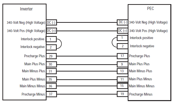
HINWEIS: Siehe die Eaton Hybrid Komponenten und Stecker-Position für Connector Standorte in MY08-Systeme
[/fusion_text][/fusion_builder_column][fusion_builder_column type=”1_1layout=”1_1spacing=”” center_content=nolink=”” target=_selfmin_height=”” hide_on_mobile=small-visibility,medium-visibility,large-visibilityclass=”” id=”” background_color=”” background_image=”” background_image_id=”” background_position=left topbackground_repeat=no-repeathover_type=noneborder_size=”0″ border_color=”” border_style=solidborder_position=allpadding_top=”” padding_right=”” padding_bottom=”” padding_left=”” margin_top=”” margin_bottom=”” animation_type=”” animation_direction=leftanimation_speed=”0.3″ animation_offset=”” last=no”][fusion_imageframe image_id=”14666|fullmax_width=”” style_type=”” blur=”” stylecolor=”” hover_type=nonebordersize=”” bordercolor=”” borderradius=”” align=centerlightbox=nogallery_id=”” lightbox_image=”” lightbox_image_id=”” alt=Inverter PEC connectors Eaton Fuller Hybrid transmissionlink=”” linktarget=_selfhide_on_mobile=small-visibility,medium-visibility,large-visibilityclass=”” id=”” animation_type=”” animation_direction=leftanimation_speed=”0.3″ animation_offset=””]https://www.globaltransmissionsupply.com/wp-content/uploads/Inverter-PEC-connectors.png[/fusion_imageframe][/fusion_builder_column][/fusion_builder_row][/fusion_builder_container][fusion_builder_container hundred_percent=nohundred_percent_height=nohundred_percent_height_scroll=nohundred_percent_height_center_content=yesequal_height_columns=nomenu_anchor=”” hide_on_mobile=small-visibility,medium-visibility,large-visibilitystatus=publishedpublish_date=”” class=”” id=”” background_color=”” background_image=”” background_position=center centerbackground_repeat=no-repeatfade=nobackground_parallax=noneenable_mobile=noparallax_speed=”0.3″ video_mp4=”” video_webm=”” video_ogv=”” video_url=”” video_aspect_ratio=”16:9″ video_loop=yesvideo_mute=yesvideo_preview_image=”” border_size=”” border_color=”” border_style=solidmargin_top=”” margin_bottom=”” padding_top=”” padding_right=”” padding_bottom=”” padding_left=””][fusion_builder_row][fusion_builder_column type=”1_1layout=”1_1spacing=”” center_content=nolink=”” target=_selfmin_height=”” hide_on_mobile=small-visibility,medium-visibility,large-visibilityclass=”” id=”” background_color=”” background_image=”” background_image_id=”” background_position=left topbackground_repeat=no-repeathover_type=noneborder_size=”0″ border_color=”” border_style=solidborder_position=allpadding_top=”” padding_right=”” padding_bottom=”” padding_left=”” margin_top=”” margin_bottom=”” animation_type=”” animation_direction=leftanimation_speed=”0.3″ animation_offset=”” last=no”][fusion_modal name=warnings_cautionstitle=”Warnungen & Verwarnungen” size=largebackground=”” border_color=”” show_footer=yesclass=”” id=””]Achtung: Gefahr bedeutet, Sie schwer verletzt werden oder getötet, wenn nicht die angegebene Prozedur folgen.
Warnung: Warnung zeigt eine unmittelbare Gefahr, die zu schweren Verletzungen führen kann, wenn Sie die angegebenen Verfahren nicht folgen.
Vorsicht: Vorsicht bedeutet, Fahrzeug oder Sachschäden können auftreten, wenn Sie die angegebene Verfahren nicht folgen.

Hinweis: Hinweis kennzeichnet zusätzliche Details, die bei der Diagnose oder Reparatur eines Bauteils / System helfen werden.

Folgen Sie das festgelegte Verfahren in der angegebenen Reihenfolge um Verletzungen zu vermeiden:

1. Wenn die Hochspannungs-Kegel sind rund um das Fahrzeug und die Sperre auf dem PEC installiert, die einzige Person, die das Fahrzeug starten erlaubt sein soll, ist die Person, die die Aussperrung Tag unterzeichnet.
2. Vor dem Arbeiten an einem Fahrzeug oder Verlassen der Kabine, während der Motor läuft, Sie sollten den Schalthebel in „N“ legen Sie die Feststellbremse eingestellt, und blockieren die Räder.
3. Aus Sicherheitsgründen, immer in Eingriff mit den Betriebsbremsen vor Gangpositionen von „N“ zu der Auswahl
4. Vor dem Start ein Fahrzeug immer auf dem Fahrersitz sitzt, Auswahl von „N“ auf der Schaltsteuerung, und die Feststellbremsen.
5. Bei Fahrzeugen mit EPTO, der Motor und / oder
Motor / Generator kann in EPTO Modus starten. Sie keine Wartungsarbeiten durchführen oder auf Fahrzeug arbeiten, in diesem Modus.
6. 12-Volt Batterie-Plus (+) und negative (-) muss vor jedem Schweiß auf jedes Hybrid ausgerüstetes Fahrzeug getrennt werden.

Vorsicht: Folgen Sie das festgelegte Verfahren in der angegebenen Reihenfolge Gerätefehlfunktionen oder Schäden zu vermeiden.
Vorsicht: Sie nicht die Feststellbremse lösen oder versuchen, einen Gang einzulegen, bis der Luftdruck auf dem richtigen Niveau ist.
Vorsicht: Um eine Beschädigung des Getriebes beim Abschleppen Ort des Schalthebels in „N“ und heben die Antriebsräder vom Boden zu vermeiden oder den Antriebsstrang trennen.

Hochspannungs-Warnungen & Verwarnungen

  • Verwenden CO2 oder Trockenlöschmittel.
  • Die Hochspannungsverdrahtung in orange Isolierung oder Wellrohr eingeschlossen und mit einer Warnetikett an den Anschlüssen bedeckt.
  • Alle Eaton® Hybrid Diesel / Elektrofahrzeuge gekennzeichnet sein wird ‚Hybrid’ auf der Außenseite des Fahrzeugs, zusammen mit dem Schiebeschild auf dem Armaturenbrett.
  • Siehe OEM für bestimmte Lage von Chassis montiert Hybridkomponenten.
  • Nicht in die orangefarbenen Hochspannungskabel geschnitten.
  • Schneiden Sie nicht in oder öffnen Sie die PEC.
  • Schneiden Sie nicht in oder öffnen Sie die DC / DC-Wandler.
  • Schneiden Sie nicht in der oder den Frequenzumrichter öffnen.

Eine Pufferzone muss und hochspannungsisoliertem Gummihandschuhen festgelegt werden (Klasse 0 mit Lederprotektoren) vor der Arbeit an Hochspannung ist erforderlich,. Die Nichtbeachtung dieser Anweisungen kann zu schweren Verletzungen oder zum Tod führt.
Die gummiisolierte Handschuhe, die während der Arbeit an der Hochspannungsanlage sind Klasse getragen werden müssen 0 mit Lederprotektoren. Die Gummihandschuhe sollten in „Diagnose-Tools / Service Publikationen“ auf Seite gefunden im Anschluss an die Gummiisolierung Handschuhe Prüfvorgang vor jedem Einsatz getestet werden 6. Die Nichtbeachtung dieser Anweisungen kann zu schweren Verletzungen oder zum Tod führt.
Vor Inspektion oder Arbeiten an allen Hochspannungskabeln oder Komponenten, die das „High-Voltage-Service Shutdown und Power-Up-Verfahrens“ auf Seite 4 sollte folgen. Die Nichtbeachtung dieser Anweisungen kann zu schweren Verletzungen oder zum Tod führt.
Die Lockout und Tagout Geräte sollten nur durch den Techniker entfernt werden, der die Sperre und Tagout Vorrichtungen am Fahrzeug platziert. Die Nichtbeachtung dieser Anweisungen kann zu schweren Verletzungen oder zum Tod führt.
Hochspannungs-Gummi-isolierte Handschuhe (Klasse 0 mit Lederprotektoren) muss getragen werden, wenn auf jedem Arbeits
Hochspannungskabel. Das „High-Voltage-Service Shutdown und Power-Up-Verfahren“ auf Seite 4 muss vor dem Entfernen aller Hochspannungskabel anschließen. Die Nichtbeachtung dieser Anweisungen kann zu schweren Verletzungen oder zum Tod führt.
Hochspannungs-Kabel und Leitungen sind orange und enthalten einen Warnhinweis an den Anschlüssen. Hochvolt-Komponenten sind mit einem Aufkleber gekennzeichnet. Hochspannungs-Gummi-isolierte Handschuhe (Klasse 0 mit Lederprotektoren) muss verwendet werden, wenn sie auf eine dieser Komponenten arbeiten. Die Nichtbeachtung dieser Anweisungen kann zu schweren Verletzungen oder zum Tod führt.

Hochspannungs-Service-Shutdown-Verfahren

Hochspannungs-Service-Shutdown und Power-Up Verfahren1. Folgen Sie „Hochspannungs-Arbeitsbereich“ Verfahren.
2. Suchen Sie den roten PEC Service Switch auf der Vorderseite des PEC und drücken ausschalten.
3. Entfernen Sie die Service-Schalterabdeckung und installieren Sie den Lockout Bracket (J48506).
4. Befestigen Tag an den Lockout Bracket.
5. Sicherstellen, dass die PEC Service Switch kann nicht von der Aus-Position bewegen.
6. Das System kann für ein Minimum einzustellen von 5 Minuten Hochspannung zu entladen,.
7. Schließen Sie den Serviceranger und Data Monitor PID anzuzeigen 116 „Hochspannungs-Batteriepotential“ genannt. Die Nutzung SPN 520323 „Batteriespannung RB“ für J1939-Anschluss (Relais-Box).
8. Die Spannung sollte sein 30 Volt oder weniger. Wenn die Spannung über 30 Volt, funktioniert nicht auf dem Fahrzeug und kontaktiert Eaton® bei 1-800-826-HELP (4357).
9. Die Zündschlüssel ab und gehen Sie zu reparieren oder Problem Schritt.
Hinweis: Die Spannung fällt auf Null, wenn der Schlüssel ausgeschaltet ist.

Hochspannungs-Service-Power-Up Verfahren

1. Installieren aller Hochspannungs-Steckverbinder in ihre verriegelten Stellungen.
2. Wenn Sie die Person, die Arbeit am Fahrzeug sind, Entfernen Sie den Lockout Bracket und Tag.
3. Setzen Sie die Lockout Halterung über den Service Switch.
4. Ziehen Sie den Service-Schalter und lassen Fahrzeug Set für 2 Protokoll.
5. Start vehicle when appropriate.[/fusion_modal][fusion_modal name=component_locationtitle=”Eaton Hybrid Komponenten und Stecker-Position ” size=largebackground=”#ffffffborder_color=”” show_footer=yesclass=”” id=””]

Eaton Hybrid Komponenten und Steckverbinder Standorte MY08-Systeme

[/fusion_modal][fusion_modal name=component_location2title=”Eaton Hybrid Komponenten und Steckverbinder Standort MY09 Systeme” size=largebackground=”#ffffffborder_color=”” show_footer=yesclass=”” id=””]

Eaton Hybrid Komponenten und Steckverbinder Standorte MY09-Systeme

[/fusion_modal][/fusion_builder_column][/fusion_builder_row][/fusion_builder_container][fusion_builder_container hundred_percent=nohundred_percent_height=nohundred_percent_height_scroll=nohundred_percent_height_center_content=yesequal_height_columns=nomenu_anchor=”” hide_on_mobile=small-visibility,medium-visibility,large-visibilitystatus=publishedpublish_date=”” class=”” id=”” background_color=”” background_image=”” background_position=center centerbackground_repeat=no-repeatfade=nobackground_parallax=noneenable_mobile=noparallax_speed=”0.3″ video_mp4=”” video_webm=”” video_ogv=”” video_url=”” video_aspect_ratio=”16:9″ video_loop=yesvideo_mute=yesvideo_preview_image=”” border_size=”” border_color=”” border_style=solidmargin_top=”” margin_bottom=”” padding_top=”” padding_right=”” padding_bottom=”” padding_left=””][fusion_builder_row][fusion_builder_column type=”1_1layout=”1_1spacing=”” center_content=nolink=”” target=_selfmin_height=”” hide_on_mobile=small-visibility,medium-visibility,large-visibilityclass=”” id=”” background_color=”” background_image=”” background_image_id=”” background_position=left topbackground_repeat=no-repeathover_type=noneborder_size=”0″ border_color=”” border_style=solidborder_position=allpadding_top=”” padding_right=”” padding_bottom=”” padding_left=”” margin_top=”” margin_bottom=”” animation_type=”” animation_direction=leftanimation_speed=”0.3″ animation_offset=”” last=no”][fusion_content_boxes layout=clean-horizontalcolumns=”2″ title_size=”18pxheading_size=”3″ title_color=”#ffffffbody_color=”#ffffffbackgroundcolor=”#4f4f4ficon=”” iconflip=”” iconrotate=”” iconspin=noiconcolor=”” icon_circle=”” icon_circle_radius=”” circlecolor=”” circlebordersize=”” circlebordercolor=”” outercirclebordersize=”” outercirclebordercolor=”” icon_size=”” icon_hover_type=”” hover_accent_color=”” image=”” image_id=”” image_width=”” image_height=”” link_type=”” button_span=”” link_area=”” link_target=”” icon_align=leftanimation_type=”” animation_delay=”” animation_offset=”” animation_direction=leftanimation_speed=”0.3″ margin_top=”” margin_bottom=”” hide_on_mobile=small-visibility,medium-visibility,large-visibilityclass=”” id=””][fusion_content_box title=SCHRITT 1. Stellen Sie sicher, FMIs vorhanden.backgroundcolor=”” icon=”” iconflip=”” iconrotate=”” iconspin=noiconcolor=”” circlecolor=”” circlebordersize=”” circlebordercolor=”” outercirclebordersize=”” outercirclebordercolor=”” image=”” image_id=”” image_width=”” image_height=”” link=”” linktext=”Weiterlesen” link_target=”” animation_type=”” animation_direction=leftanimation_speed=”0.3″ animation_offset=””]

  1. Überprüfen Sie und folgen Sie den Warnungen & Verwarnungen.
  2. Rufen Sie aktive Fehlercodes und FMI mit Serviceranger den 9-Way Diagnosestecker mit.
    Achtung: Sehen Hochspannungs-Service-Shutdown und Power-Up Verfahren. Folgen Sie den Anweisungen Schock zu vermeiden, verbrennen oder Tod durch unsachgemäß behandelt Hochspannungs-.
  3. Welche FMIs vorhanden sind
    • Wenn Fehlercode 116 IWF 14 ist aufgelistet, gehen Sie zu Schritt 9.
    • Wenn Fehlercode 116 IWF 10 ist aufgelistet, gehen Sie zu Schritt 2.
    • If no Fault Codes are listed, The Service Switch was pushed in. Weiter mit Schritt 10.

[/fusion_content_box][fusion_content_box title=SCHRITT 2. Verify Data Monitor parameters.backgroundcolor=”” icon=”” iconflip=”” iconrotate=”” iconspin=noiconcolor=”” circlecolor=”” circlebordersize=”” circlebordercolor=”” outercirclebordersize=”” outercirclebordercolor=”” image=”” image_id=”” image_width=”” image_height=”” link=”” linktext=”Weiterlesen” link_target=”” animation_type=”” animation_direction=leftanimation_speed=”0.3″ animation_offset=””]

  1. Key auf.
  2. Verbinden Serviceranger an den 9-Wege-Diagnosestecker in der Kabine.
  3. Wählen Sie die „Data Monitor“ Option.
  4. View the Battery Pack Voltage (BCU1) PID 118 in the high- voltage Battery list:
    • If the Battery Pack Voltage (BCU1) PID 118 is greater than 200 Volt, gehen Sie zu Schritt 3.
    • If the Battery Pack Voltage (BCU1) PID 118 ist weniger als 200 Volt, ersetzen Sie die Leistungselektronik Träger (PEC), dann weiter mit Schritt 10.

[/fusion_content_box][/fusion_content_boxes][fusion_content_boxes layout=clean-horizontalcolumns=”2″ title_size=”18pxheading_size=”3″ title_color=”#ffffffbody_color=”#ffffffbackgroundcolor=”#4f4f4ficon=”” iconflip=”” iconrotate=”” iconspin=noiconcolor=”” icon_circle=”” icon_circle_radius=”” circlecolor=”” circlebordersize=”” circlebordercolor=”” outercirclebordersize=”” outercirclebordercolor=”” icon_size=”” icon_hover_type=”” hover_accent_color=”” image=”” image_id=”” image_width=”” image_height=”” link_type=”” button_span=”” link_area=”” link_target=”” icon_align=leftanimation_type=”” animation_delay=”” animation_offset=”” animation_direction=leftanimation_speed=”0.3″ margin_top=”” margin_bottom=”” hide_on_mobile=small-visibility,medium-visibility,large-visibilityclass=”” id=””][fusion_content_box title=SCHRITT 3. Verify continuity of Inverter connector circuits.backgroundcolor=”” icon=”” iconflip=”” iconrotate=”” iconspin=noiconcolor=”” circlecolor=”” circlebordersize=”” circlebordercolor=”” outercirclebordersize=”” outercirclebordercolor=”” image=”” image_id=”” image_width=”” image_height=”” link=”” linktext=”Weiterlesen” link_target=”” animation_type=”” animation_direction=leftanimation_speed=”0.3″ animation_offset=””]

  1. Schlüssel aus.
  2. If the vehicle is not equipped with a DC/DC Converter or APG, skip this step.
  3. Using ASTM Class 0 electrical insulating rubber gloves with leather protectors, disconnect the DC cable for the DC/DC Converter and APG at the PEC.
  4. With the key off, temporarily remove the Lockout Bracket and pull the Service Switch out.
  5. Key auf.
  6. Ist Fehlercode 116 IWF 10 still Active in ServiceRanger?
    • Wenn Fehlercode 116 IWF 10 is Active with the DC/DC Converter and APG disconnected, gehen Sie zu Schritt 4.
    • Wenn Fehlercode 116 IWF 10 is no longer Active with the DC/DC Converter and APG disconnected, key off and reinstall the Lockout Bracket on the PEC. Replace the Power Electronics Carrier (PEC), dann weiter mit Schritt 10.

[/fusion_content_box][fusion_content_box title=SCHRITT 4. Verify continuity of PEC connector circuits to ground.backgroundcolor=”” icon=”” iconflip=”” iconrotate=”” iconspin=”” iconcolor=”” circlecolor=”” circlebordersize=”” circlebordercolor=”” outercirclebordersize=”” outercirclebordercolor=”” image=”” image_id=”” image_width=”” image_height=”” link=”” linktext=”” link_target=”” animation_type=”” animation_direction=leftanimation_speed=”0.3″ animation_offset=””]

  1. Schlüssel aus.
  2. Ziehen Sie den PEC 19-poligen Stecker.
  3. Temporarily remove the Lockout Bracket and pull the Service Switch out.
    Hinweis: Ensure the Key Switch is off.
  4. Measure resistance at the PEC 19-Way Connector Terminal at the following pins:
    • Stift 17 anheften 19
    • Stift 9 anheften 11
    • Stift 13 anheften 15
      • If the resistance between Pins 17 und Pin 19 beträgt 112-122 Ohm und der Widerstand von Pin 9 anheften 11 und Pin 13 anheften 15 jeweils 33-37 Ohm, gehen Sie zu Schritt 5.
      • Wenn der Widerstand Bereich aus, gehen Sie zu Schritt 6.

[/fusion_content_box][/fusion_content_boxes][fusion_content_boxes layout=clean-horizontalcolumns=”2″ title_size=”18pxheading_size=”3″ title_color=”#ffffffbody_color=”#ffffffbackgroundcolor=”#4f4f4ficon=”” iconflip=”” iconrotate=”” iconspin=noiconcolor=”” icon_circle=”” icon_circle_radius=”” circlecolor=”” circlebordersize=”” circlebordercolor=”” outercirclebordersize=”” outercirclebordercolor=”” icon_size=”” icon_hover_type=”” hover_accent_color=”” image=”” image_id=”” image_width=”” image_height=”” link_type=”” button_span=”” link_area=”” link_target=”” icon_align=leftanimation_type=”” animation_delay=”” animation_offset=”” animation_direction=leftanimation_speed=”0.3″ margin_top=”” margin_bottom=”” hide_on_mobile=small-visibility,medium-visibility,large-visibilityclass=”” id=””][fusion_content_box title=SCHRITT 5. Verify continuity of Inverter connector circuits to ground.backgroundcolor=”” icon=”” iconflip=”” iconrotate=”” iconspin=noiconcolor=”” circlecolor=”” circlebordersize=”” circlebordercolor=”” outercirclebordersize=”” outercirclebordercolor=”” image=”” image_id=”” image_width=”” image_height=”” link=”” linktext=”Weiterlesen” link_target=”” animation_type=”” animation_direction=leftanimation_speed=”0.3″ animation_offset=””]

  1. Schlüssel aus.
  2. Reconnect the PEC 19-Way Connector.
  3. Den Wechselrichter 56-poligen Stecker.
  4. Inspect the connector pins for damaged, corroded and/or loose wires.
  5. Measure resistance between the Inverter 56-Way Connector at the following pins:
    • Stift 29 anheften 37
    • Stift 30 anheften 35
    • Stift 31 anheften 36 Hinweis: den Inverter 56-poligen Stecker Harness nahe dem Verbindungsstück sanft biegen, während die Widerstandswerte Überwachungs.
      • Wenn der Widerstand zwischen Pin 29 und Pin 37 beträgt 112-122 Ohm und der Widerstand von Pin 30 anheften 35 und Pin 31 anheften 36 jeweils 33-37 Ohm, push the Service Switch on the PEC and reinstall the Lockout Bracket. Weiter mit Schritt 8.
      • Wenn der Widerstand Bereich aus, repair the Hybrid Harness between the PEC and Inverter, dann weiter mit Schritt 10.

[/fusion_content_box][fusion_content_box title=SCHRITT 6. Verify continuity of PEC connector circuits.backgroundcolor=”” icon=”” iconflip=”” iconrotate=”” iconspin=”” iconcolor=”” circlecolor=”” circlebordersize=”” circlebordercolor=”” outercirclebordersize=”” outercirclebordercolor=”” image=”” image_id=”” image_width=”” image_height=”” link=”” linktext=”” link_target=”” animation_type=”” animation_direction=leftanimation_speed=”0.3″ animation_offset=””]

  1. Schlüssel aus.
  2. Remove the Air Filter Cover and Air Filter from the PEC. Refer to TRSM1000 for procedures.*
  3. An Inertia Switch is located at the front of the PEC inside the box and viewable when the Air Filter is removed.
  4. Using ASTM Class 0 electrical insulating rubber gloves with leather protectors, press the button on the top of the Inertia Switch until heard or felt a click. This switch must be depressed a set distance to reset the switch.
  5. Measure resistance at the PEC 19-Way Connector Terminal at the following pins:
    • Stift 17 anheften 19
    • Stift 9 anheften 11
    • Stift 13 anheften 15
      • qIf the resistance between Pin 17 und Pin 19 beträgt 112-122 Ohm und der Widerstand von Pin 9 anheften 11 und Pin 13 anheften 15 jeweils 33-37 Ohm, the Inertia Switch was tripped. Test is complete. Weiter mit Schritt 10.
      • Wenn der Widerstand Bereich aus, push in the Service Switch on the PEC and reinstall the Lockout Bracket, dann weiter mit Schritt 7.

[/fusion_content_box][/fusion_content_boxes][fusion_content_boxes layout=clean-horizontalcolumns=”2″ title_size=”18pxheading_size=”3″ title_color=”#ffffffbody_color=”#ffffffbackgroundcolor=”#4f4f4ficon=”” iconflip=”” iconrotate=”” iconspin=noiconcolor=”” icon_circle=”” icon_circle_radius=”” circlecolor=”” circlebordersize=”” circlebordercolor=”” outercirclebordersize=”” outercirclebordercolor=”” icon_size=”” icon_hover_type=”” hover_accent_color=”” image=”” image_id=”” image_width=”” image_height=”” link_type=”” button_span=”” link_area=”” link_target=”” icon_align=leftanimation_type=”” animation_delay=”” animation_offset=”” animation_direction=leftanimation_speed=”0.3″ margin_top=”” margin_bottom=”” hide_on_mobile=small-visibility,medium-visibility,large-visibilityclass=”” id=””][fusion_content_box title=SCHRITT 7. Verify continuity of Inverter connector circuits.backgroundcolor=”” icon=”” iconflip=”” iconrotate=”” iconspin=noiconcolor=”” circlecolor=”” circlebordersize=”” circlebordercolor=”” outercirclebordersize=”” outercirclebordercolor=”” image=”” image_id=”” image_width=”” image_height=”” link=”” linktext=”Weiterlesen” link_target=”” animation_type=”” animation_direction=leftanimation_speed=”0.3″ animation_offset=””]

  1. Schlüssel aus.
  2. Disconnect the DC High-Voltage Cable at the PEC Bulkhead and at the Inverter Bulkhead.
  3. Measure resistance between the Low-Voltage Interlock Pins on the PEC side of the DC High-Voltage Cable:
    Hinweis: The Interlock Pins are the two small spade terminals located in the same opening.

    • If the resistance is 0–0.3 ohms between the Interlock Loop Pins, ersetzen Sie die Leistungselektronik Träger (PEC), dann weiter mit Schritt 10.
    • Wenn der Widerstand Bereich aus, den DC-Hochspannungskabel ersetzen, dann weiter mit Schritt 10.

[/fusion_content_box][fusion_content_box title=SCHRITT 8. Verify continuity of DC Cable from PEC to Inverter Connector circuits.backgroundcolor=”” icon=”” iconflip=”” iconrotate=”” iconspin=”” iconcolor=”” circlecolor=”” circlebordersize=”” circlebordercolor=”” outercirclebordersize=”” outercirclebordercolor=”” image=”” image_id=”” image_width=”” image_height=”” link=”” linktext=”” link_target=”” animation_type=”” animation_direction=leftanimation_speed=”0.3″ animation_offset=””]

  1. Schlüssel aus.
  2. Disconnect the DC High-Voltage Cable at the PEC Bulkhead and the Inverter Bulkhead.
  3. Measure the resistance of each high-voltage circuit on the cable:
    • If the resistance of each high-voltage circuit in the cable is 1 Ohm oder weniger, ersetzen Sie den Inverter, dann weiter mit Schritt 10.
    • Wenn der Widerstand Bereich aus, replace the DC High-Voltage Cable, dann weiter mit Schritt 10.

[/fusion_content_box][/fusion_content_boxes][fusion_content_boxes layout=clean-horizontalcolumns=”2″ title_size=”18pxheading_size=”3″ title_color=”#ffffffbody_color=”#ffffffbackgroundcolor=”#4f4f4ficon=”” iconflip=”” iconrotate=”” iconspin=noiconcolor=”” icon_circle=”” icon_circle_radius=”” circlecolor=”” circlebordersize=”” circlebordercolor=”” outercirclebordersize=”” outercirclebordercolor=”” icon_size=”” icon_hover_type=”” hover_accent_color=”#f41000image=”” image_id=”” image_width=”” image_height=”” link_type=”” button_span=”” link_area=”” link_target=”” icon_align=leftanimation_type=”” animation_delay=”” animation_offset=”” animation_direction=leftanimation_speed=”0.3″ margin_top=”” margin_bottom=”” hide_on_mobile=small-visibility,medium-visibility,large-visibilityclass=”” id=””][fusion_content_box title=SCHRITT 9. Verify Data Monitor parameters.backgroundcolor=”” icon=”” iconflip=”” iconrotate=”” iconspin=”” iconcolor=”” circlecolor=”” circlebordersize=”” circlebordercolor=”” outercirclebordersize=”” outercirclebordercolor=”” image=”” image_id=”” image_width=”” image_height=”” link=”” linktext=”” link_target=”” animation_type=”” animation_direction=leftanimation_speed=”0.3″ animation_offset=””]

  1. Verbinden Serviceranger an den 9-Wege-Diagnosestecker in der Kabine.
  2. Wählen Sie die „Data Monitor“ Option.
  3. View the following parameters in the High-Voltage Battery list.
    • Battery Pack Voltage (BCU1) PID 118
    • Battery Voltage PID 116
      • If the voltage readings on PID 116 und PID 118 are within 10 Volt voneinander, ersetzen Sie die Leistungselektronik Träger (PEC), dann weiter mit Schritt 10.
      • If the voltage readings on PID 116 und PID 118 are greater than 10 Volt voneinander, ersetzen Sie den Inverter, dann weiter mit Schritt 10.

[/fusion_content_box][fusion_content_box title=SCHRITT 10. Reparatur überprüfen.backgroundcolor=”” icon=”” iconflip=”” iconrotate=”” iconspin=noiconcolor=”” circlecolor=”” circlebordersize=”” circlebordercolor=”” outercirclebordersize=”” outercirclebordercolor=”” image=”” image_id=”” image_width=”” image_height=”” link=”” linktext=”Weiterlesen” link_target=”” animation_type=”” animation_direction=leftanimation_speed=”0.3″ animation_offset=””]

  1. Schlüssel aus.
  2. Schließen Sie alle Anschlüsse und die negativen Batteriekabel.
  3. Key auf.
  4. Codes löschen, sehen Klar Inaktive Fehler.
  5. Fahren Sie das Fahrzeug und versuchen, den Code neu.
  6. Prüfen Sie, ob Codes, sehen Sehen Sie Aktive und inaktive Fehler.
    • Wenn keine Codes, Test abgeschlossen.
    • Wenn Fehlercode 116 erscheint, Kontakt Eaton bei 1- 800-826-HILFE (4357). Repeat this Step (Schritt 10).
    • Wenn ein anderer Code als 116 erscheint, sehen Fehlercode Indexliste.

[/fusion_content_box][/fusion_content_boxes][/fusion_builder_column][/fusion_builder_row][/fusion_builder_container][fusion_global id=”13788″]