[fusion_builder_container hundred_percent=”yes” hundred_percent_height=”no” hundred_percent_height_scroll=”no” hundred_percent_height_center_content=”yes” equal_height_columns=”no” menu_anchor=”” hide_on_mobile=”small-visibility,medium-visibility,large-visibility” status=”published” publish_date=”” class=”” id=”” background_color=”” background_image=”” background_position=”center center” background_repeat=”no-repeat” fade=”no” background_parallax=”none” enable_mobile=”no” parallax_speed=”0.3″ video_mp4=”” video_webm=”” video_ogv=”” video_url=”” video_aspect_ratio=”16:9″ video_loop=”yes” video_mute=”yes” video_preview_image=”” border_size=”” border_color=”” border_style=”solid” margin_top=”35″ margin_bottom=”” padding_top=”” padding_right=”” padding_bottom=”” padding_left=””][fusion_builder_row][fusion_builder_column type=”1_1″ layout=”1_1″ spacing=”” center_content=”no” link=”” target=”_self” min_height=”” hide_on_mobile=”small-visibility,medium-visibility,large-visibility” class=”” id=”” background_color=”” background_image=”” background_image_id=”” background_position=”left top” background_repeat=”no-repeat” hover_type=”none” border_size=”0″ border_color=”” border_style=”solid” border_position=”all” padding_top=”” padding_right=”” padding_bottom=”” padding_left=”” margin_top=”” margin_bottom=”” animation_type=”” animation_direction=”left” animation_speed=”0.3″ animation_offset=”” last=”no”][fusion_text columns=”” column_min_width=”” column_spacing=”” rule_style=”default” rule_size=”” rule_color=”” hide_on_mobile=”small-visibility,medium-visibility,large-visibility” class=”” id=””]
Eaton Fuller Hybrid Fehlercode 1 Motor-Generator Stromsensor
[/fusion_text][/fusion_builder_column][/fusion_builder_row][/fusion_builder_container][fusion_builder_container hundred_percent=”no” hundred_percent_height=”no” hundred_percent_height_scroll=”no” hundred_percent_height_center_content=”yes” equal_height_columns=”no” menu_anchor=”” hide_on_mobile=”small-visibility,medium-visibility,large-visibility” status=”published” publish_date=”” class=”” id=”” background_color=”” background_image=”” background_position=”center center” background_repeat=”no-repeat” fade=”no” background_parallax=”none” enable_mobile=”no” parallax_speed=”0.3″ video_mp4=”” video_webm=”” video_ogv=”” video_url=”” video_aspect_ratio=”16:9″ video_loop=”yes” video_mute=”yes” video_preview_image=”” border_size=”” border_color=”” border_style=”solid” margin_top=”” margin_bottom=”” padding_top=”” padding_right=”” padding_bottom=”” padding_left=””][fusion_builder_row][fusion_builder_column type=”1_1″ layout=”1_1″ spacing=”” center_content=”no” link=”” target=”_self” min_height=”” hide_on_mobile=”small-visibility,medium-visibility,large-visibility” class=”” id=”” background_color=”” background_image=”” background_image_id=”” background_position=”left top” background_repeat=”no-repeat” hover_type=”none” border_size=”0″ border_color=”” border_style=”solid” border_position=”all” padding_top=”” padding_right=”” padding_bottom=”” padding_left=”” margin_top=”” margin_bottom=”” animation_type=”” animation_direction=”left” animation_speed=”0.3″ animation_offset=”” last=”no”][fusion_text columns=”” column_min_width=”” column_spacing=”” rule_style=”default” rule_size=”” rule_color=”” hide_on_mobile=”small-visibility,medium-visibility,large-visibility” class=”” id=””]
Fehlercode für Eaton Hybrid Drive System Modelle (MY08) EH-U-8E306A, EH-8E306A-UPG, EH-8E306A-UP, EH-8E306A-CD, EH-8E306A-T, EH-6E606B-CD, (MY09) EH-8E406A-U / P, EH-8E406A-UP, EH-8E406A-UPG, EH-8E406A-CD, EH-8E406A-CDG, EH-8E406A-CDR, EH-8E406A-T, EH-6E706B-CD, EH-6E706B-P und EH-6E706B-UPG. The High-Voltage Motor/Generator Assembly is connected to the Inverter Assembly through an AC High-Voltage Cable that contains 3 separate Kabel. Während der Operation, the Inverter monitors the amperage in the AC cables through a current sensor, die innerhalb des Inverter montiert. The inductive sensor produces an output based on amperage present in the cables.
Falscher Code 1 Motor / Generator Stromsensorerkennung
Die Inverter-Zündspannung größer ist als 7 Volt und weniger als 16 Volt.
Bedingungen setzen Fehlercode Aktiv
Bedingungen einzustellen Fehler:
- IWF 6 is set when Inverter detects current input from the Motor/Generator greater than 100 A für 150 FRAU.
- IWF 0 is set when the Inverter detects current input from the Motor/Generator greater than 200 A für 0.3 FRAU.
- IWF 15 is set when the sensor offset is out of range at initial check.
Notlösung, wenn Fehlercode 1 die folgenden Bedingungen auftreten, eingestellt ist:
• Gelb „prüfen Hybrid“ Licht leuchtet.
• Fehler in Hybrid-Steuermodul gespeichert (HCM) Erinnerung.
• Elektromotor-/Generatorunterstützung und Regeneration sind deaktiviert; jedoch, die Hochspannungsrelais bleiben angetriebene.
• HCM steuert das Hybridfahrzeug weiterhin im reinen Dieselmodus.
• Übertragung Standardwerte starten Gang 1..
[/fusion_text][fusion_text columns=”” column_min_width=”” column_spacing=”” rule_style=”default” rule_size=”” rule_color=”” hide_on_mobile=”small-visibility,medium-visibility,large-visibility” class=”” id=””]
Bedingungen einzustellen Fehlercode Inaktive
Nur inaktive Fehler können von der Transmission Electronic Control Unit gelöscht werden (TECU) oder HCM Geschichte mit Serviceranger. Die TECU löscht automatisch die Fehler aus der Geschichte nach dem 200 hours and the HCM automatically clears the faults from history after the fault has stayed Inactive for 200 Std.
Dieser Fehlercode kann durch eine der folgenden Bedingungen verursacht werden:
- IWF 0, 6
- Wandler
- Motor / Generator
- AC-Kabel
- IWF 15
- Wandler
[/fusion_text][/fusion_builder_column][/fusion_builder_row][/fusion_builder_container][fusion_builder_container hundred_percent=”no” hundred_percent_height=”no” hundred_percent_height_scroll=”no” hundred_percent_height_center_content=”yes” equal_height_columns=”no” menu_anchor=”” hide_on_mobile=”small-visibility,medium-visibility,large-visibility” status=”published” publish_date=”” class=”” id=”” background_color=”” background_image=”” background_position=”center center” background_repeat=”no-repeat” fade=”no” background_parallax=”none” enable_mobile=”no” parallax_speed=”0.3″ video_mp4=”” video_webm=”” video_ogv=”” video_url=”” video_aspect_ratio=”16:9″ video_loop=”yes” video_mute=”yes” video_preview_image=”” border_size=”” border_color=”” border_style=”solid” margin_top=”” margin_bottom=”” padding_top=”” padding_right=”” padding_bottom=”” padding_left=””][fusion_builder_row][fusion_builder_column type=”1_1″ layout=”1_1″ spacing=”” center_content=”no” link=”” target=”_self” min_height=”” hide_on_mobile=”small-visibility,medium-visibility,large-visibility” class=”” id=”” background_color=”” background_image=”” background_image_id=”” background_position=”left top” background_repeat=”no-repeat” hover_type=”none” border_size=”0″ border_color=”” border_style=”solid” border_position=”all” padding_top=”” padding_right=”” padding_bottom=”” padding_left=”” margin_top=”” margin_bottom=”” animation_type=”” animation_direction=”left” animation_speed=”0.3″ animation_offset=”” last=”no”][fusion_text columns=”” column_min_width=”” column_spacing=”” rule_style=”default” rule_size=”” rule_color=”” hide_on_mobile=”small-visibility,medium-visibility,large-visibility” class=”” id=””]
Falscher Code 1 – Motor / Generator Strom-Sensor-Test
[/fusion_text][/fusion_builder_column][/fusion_builder_row][/fusion_builder_container][fusion_builder_container hundred_percent=”no” hundred_percent_height=”no” hundred_percent_height_scroll=”no” hundred_percent_height_center_content=”yes” equal_height_columns=”no” menu_anchor=”” hide_on_mobile=”small-visibility,medium-visibility,large-visibility” status=”published” publish_date=”” class=”” id=”” background_color=”” background_image=”” background_position=”center center” background_repeat=”no-repeat” fade=”no” background_parallax=”none” enable_mobile=”no” parallax_speed=”0.3″ video_mp4=”” video_webm=”” video_ogv=”” video_url=”” video_aspect_ratio=”16:9″ video_loop=”yes” video_mute=”yes” video_preview_image=”” border_size=”” border_color=”” border_style=”solid” margin_top=”” margin_bottom=”” padding_top=”” padding_right=”” padding_bottom=”” padding_left=””][fusion_builder_row][fusion_builder_column type=”1_1″ layout=”1_1″ spacing=”” center_content=”no” link=”” target=”_self” min_height=”” hide_on_mobile=”small-visibility,medium-visibility,large-visibility” class=”” id=”” background_color=”” background_image=”” background_image_id=”” background_position=”left top” background_repeat=”no-repeat” hover_type=”none” border_size=”0″ border_color=”” border_style=”solid” border_position=”all” padding_top=”” padding_right=”” padding_bottom=”” padding_left=”” margin_top=”” margin_bottom=”” animation_type=”” animation_direction=”left” animation_speed=”0.3″ animation_offset=”” last=”no”][fusion_text columns=”” column_min_width=”” column_spacing=”” rule_style=”default” rule_size=”” rule_color=”” hide_on_mobile=”small-visibility,medium-visibility,large-visibility” class=”” id=””]
Identifizierung der Komponenten MY08-System:
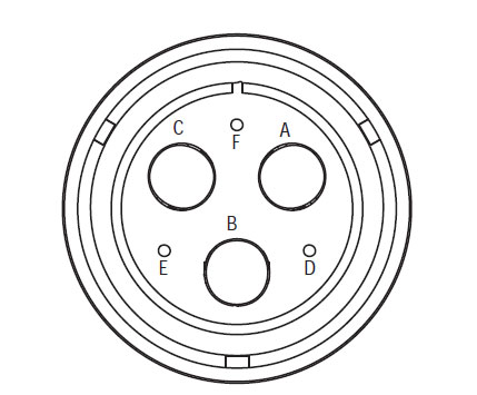
[/fusion_text][/fusion_builder_column][fusion_builder_column type=”1_2″ layout=”1_2″ spacing=”” center_content=”no” link=”” target=”_self” min_height=”” hide_on_mobile=”small-visibility,medium-visibility,large-visibility” class=”” id=”” background_color=”” background_image=”” background_image_id=”” background_position=”left top” background_repeat=”no-repeat” hover_type=”none” border_size=”0″ border_color=”” border_style=”solid” border_position=”all” padding_top=”” padding_right=”” padding_bottom=”” padding_left=”” margin_top=”” margin_bottom=”” animation_type=”” animation_direction=”left” animation_speed=”0.3″ animation_offset=”” last=”no”][fusion_imageframe image_id=”13902|full” max_width=”” style_type=”” blur=”” stylecolor=”” hover_type=”none” bordersize=”” bordercolor=”” borderradius=”” align=”center” lightbox=”no” gallery_id=”” lightbox_image=”” lightbox_image_id=”” alt=”Hochspannungs-Wechselstrom-Harness-Connector Ansicht” link=”” linktarget=”_self” hide_on_mobile=”small-visibility,medium-visibility,large-visibility” class=”” id=”” animation_type=”” animation_direction=”left” animation_speed=”0.3″ animation_offset=””]https://www.globaltransmissionsupply.com/wp-content/uploads/High-Voltage-AC-Harness-Connector-View.jpg[/fusion_imageframe][fusion_text columns=”” column_min_width=”” column_spacing=”” rule_style=”default” rule_size=”” rule_color=”” hide_on_mobile=”small-visibility,medium-visibility,large-visibility” class=”” id=””]
Hochspannungs-Wechselstrom-Harness-Connector Ansicht
(Amphenol-Anschluss)
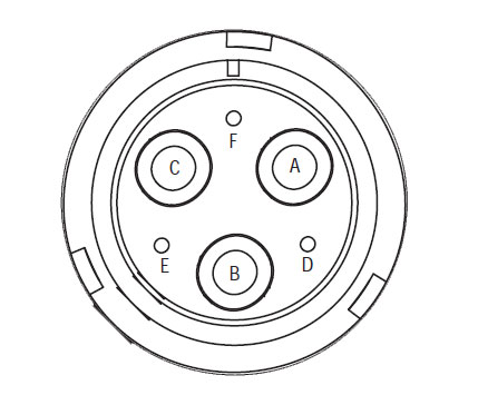
[/fusion_text][/fusion_builder_column][fusion_builder_column type=”1_2″ layout=”1_2″ spacing=”” center_content=”no” link=”” target=”_self” min_height=”” hide_on_mobile=”small-visibility,medium-visibility,large-visibility” class=”” id=”” background_color=”” background_image=”” background_image_id=”” background_position=”left top” background_repeat=”no-repeat” hover_type=”none” border_size=”0″ border_color=”” border_style=”solid” border_position=”all” padding_top=”” padding_right=”” padding_bottom=”” padding_left=”” margin_top=”” margin_bottom=”” animation_type=”” animation_direction=”left” animation_speed=”0.3″ animation_offset=”” last=”no”][fusion_imageframe image_id=”13903|full” max_width=”” style_type=”” blur=”” stylecolor=”” hover_type=”none” bordersize=”” bordercolor=”” borderradius=”” align=”center” lightbox=”no” gallery_id=”” lightbox_image=”” lightbox_image_id=”” alt=”Hochspannungs-Wechselstrom-Motor / Gen-Anschluss anzeigen ” link=”” linktarget=”_self” hide_on_mobile=”small-visibility,medium-visibility,large-visibility” class=”” id=”” animation_type=”” animation_direction=”left” animation_speed=”0.3″ animation_offset=””]https://www.globaltransmissionsupply.com/wp-content/uploads/High-Voltage-AC-Motor-Gen-Connector-View.jpg[/fusion_imageframe][fusion_text columns=”” column_min_width=”” column_spacing=”” rule_style=”default” rule_size=”” rule_color=”” hide_on_mobile=”small-visibility,medium-visibility,large-visibility” class=”” id=””]
Hochspannungs-Wechselstrom-Motor / Gen-Anschluss anzeigen
(Amphenol-Anschluss)
[/fusion_text][/fusion_builder_column][fusion_builder_column type=”1_1″ layout=”1_1″ spacing=”” center_content=”no” link=”” target=”_self” min_height=”” hide_on_mobile=”small-visibility,medium-visibility,large-visibility” class=”” id=”” background_image_id=”” background_color=”#000000″ background_image=”” background_position=”left top” undefined=”” background_repeat=”no-repeat” hover_type=”none” border_size=”0″ border_color=”” border_style=”solid” border_position=”all” padding_top=”” padding_right=”” padding_bottom=”” padding_left=”” margin_top=”” margin_bottom=”10″ animation_type=”” animation_direction=”left” animation_speed=”0.3″ animation_offset=”” last=”no”][fusion_text columns=”” column_min_width=”” column_spacing=”” rule_style=”default” rule_size=”” rule_color=”” hide_on_mobile=”small-visibility,medium-visibility,large-visibility” class=”” id=””]
HINWEIS: Siehe die Eaton Hybrid Komponenten und Stecker-Position für Connector Standorte in MY08-Systeme
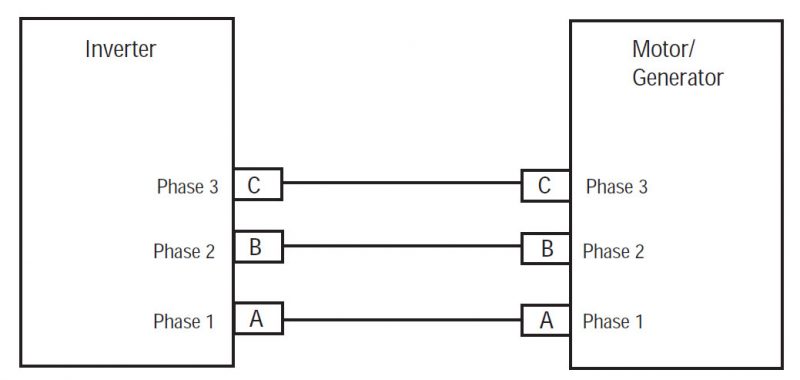
[/fusion_text][/fusion_builder_column][fusion_builder_column type=”1_1″ layout=”1_1″ spacing=”” center_content=”no” link=”” target=”_self” min_height=”” hide_on_mobile=”small-visibility,medium-visibility,large-visibility” class=”” id=”” background_color=”” background_image=”” background_image_id=”” background_position=”left top” background_repeat=”no-repeat” hover_type=”none” border_size=”0″ border_color=”” border_style=”solid” border_position=”all” padding_top=”” padding_right=”” padding_bottom=”” padding_left=”” margin_top=”” margin_bottom=”” animation_type=”” animation_direction=”left” animation_speed=”0.3″ animation_offset=”” last=”no”][fusion_imageframe image_id=”13904|800″ max_width=”” style_type=”” blur=”” stylecolor=”” hover_type=”none” bordersize=”” bordercolor=”” borderradius=”” align=”center” lightbox=”no” gallery_id=”” lightbox_image=”” lightbox_image_id=”” alt=”Komponentanschluss” link=”” linktarget=”_self” hide_on_mobile=”small-visibility,medium-visibility,large-visibility” class=”” id=”” animation_type=”” animation_direction=”left” animation_speed=”0.3″ animation_offset=””]https://www.globaltransmissionsupply.com/wp-content/uploads/eaton-component-connector-800×380.jpg[/fusion_imageframe][/fusion_builder_column][/fusion_builder_row][/fusion_builder_container][fusion_builder_container hundred_percent=”no” hundred_percent_height=”no” hundred_percent_height_scroll=”no” hundred_percent_height_center_content=”yes” equal_height_columns=”no” menu_anchor=”” hide_on_mobile=”small-visibility,medium-visibility,large-visibility” status=”published” publish_date=”” class=”” id=”” background_color=”” background_image=”” background_position=”center center” background_repeat=”no-repeat” fade=”no” background_parallax=”none” enable_mobile=”no” parallax_speed=”0.3″ video_mp4=”” video_webm=”” video_ogv=”” video_url=”” video_aspect_ratio=”16:9″ video_loop=”yes” video_mute=”yes” video_preview_image=”” border_size=”” border_color=”” border_style=”solid” margin_top=”” margin_bottom=”” padding_top=”” padding_right=”” padding_bottom=”” padding_left=””][fusion_builder_row][fusion_builder_column type=”1_1″ layout=”1_1″ spacing=”” center_content=”no” link=”” target=”_self” min_height=”” hide_on_mobile=”small-visibility,medium-visibility,large-visibility” class=”” id=”” background_color=”” background_image=”” background_image_id=”” background_position=”left top” background_repeat=”no-repeat” hover_type=”none” border_size=”0″ border_color=”” border_style=”solid” border_position=”all” padding_top=”” padding_right=”” padding_bottom=”” padding_left=”” margin_top=”” margin_bottom=”” animation_type=”” animation_direction=”left” animation_speed=”0.3″ animation_offset=”” last=”no”][fusion_text columns=”” column_min_width=”” column_spacing=”” rule_style=”default” rule_size=”” rule_color=”” hide_on_mobile=”small-visibility,medium-visibility,large-visibility” class=”” id=””]
Identifizierung der Komponenten MY09-System:
[/fusion_text][/fusion_builder_column][fusion_builder_column type=”1_2″ layout=”1_2″ spacing=”” center_content=”no” link=”” target=”_self” min_height=”” hide_on_mobile=”small-visibility,medium-visibility,large-visibility” class=”” id=”” background_color=”” background_image=”” background_image_id=”” background_position=”left top” background_repeat=”no-repeat” hover_type=”none” border_size=”0″ border_color=”” border_style=”solid” border_position=”all” padding_top=”” padding_right=”” padding_bottom=”” padding_left=”” margin_top=”” margin_bottom=”” animation_type=”” animation_direction=”left” animation_speed=”0.3″ animation_offset=”” last=”no”][fusion_imageframe image_id=”13902|full” max_width=”” style_type=”” blur=”” stylecolor=”” hover_type=”none” bordersize=”” bordercolor=”” borderradius=”” align=”center” lightbox=”no” gallery_id=”” lightbox_image=”” lightbox_image_id=”” alt=”Hochspannungs-Wechselstrom-Harness-Connector Ansicht” link=”” linktarget=”_self” hide_on_mobile=”small-visibility,medium-visibility,large-visibility” class=”” id=”” animation_type=”” animation_direction=”left” animation_speed=”0.3″ animation_offset=””]https://www.globaltransmissionsupply.com/wp-content/uploads/High-Voltage-AC-Harness-Connector-View.jpg[/fusion_imageframe][fusion_text columns=”” column_min_width=”” column_spacing=”” rule_style=”default” rule_size=”” rule_color=”” hide_on_mobile=”small-visibility,medium-visibility,large-visibility” class=”” id=””]
Hochspannungs-Wechselstrom-Harness-Connector Ansicht
(Amphenol-Anschluss)
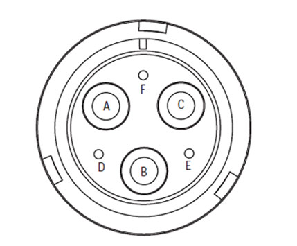
[/fusion_text][/fusion_builder_column][fusion_builder_column type=”1_2″ layout=”1_2″ spacing=”” center_content=”no” link=”” target=”_self” min_height=”” hide_on_mobile=”small-visibility,medium-visibility,large-visibility” class=”” id=”” background_color=”” background_image=”” background_image_id=”” background_position=”left top” background_repeat=”no-repeat” hover_type=”none” border_size=”0″ border_color=”” border_style=”solid” border_position=”all” padding_top=”” padding_right=”” padding_bottom=”” padding_left=”” margin_top=”” margin_bottom=”” animation_type=”” animation_direction=”left” animation_speed=”0.3″ animation_offset=”” last=”no”][fusion_imageframe image_id=”14034|full” max_width=”” style_type=”” blur=”” stylecolor=”” hover_type=”none” bordersize=”” bordercolor=”” borderradius=”” align=”center” lightbox=”no” gallery_id=”” lightbox_image=”” lightbox_image_id=”” alt=”Hochspannungs-Wechselstrom-Motor / Gen-Anschluss anzeigen ” link=”” linktarget=”_self” hide_on_mobile=”small-visibility,medium-visibility,large-visibility” class=”” id=”” animation_type=”” animation_direction=”left” animation_speed=”0.3″ animation_offset=””]https://www.globaltransmissionsupply.com/wp-content/uploads/High-Voltage-AC-Motor-Gen-Connector-View-MY09.jpg[/fusion_imageframe][fusion_text columns=”” column_min_width=”” column_spacing=”” rule_style=”default” rule_size=”” rule_color=”” hide_on_mobile=”small-visibility,medium-visibility,large-visibility” class=”” id=””]
Hochspannungs-Wechselstrom-Motor / Gen-Anschluss anzeigen
(Amphenol-Anschluss)
[/fusion_text][/fusion_builder_column][fusion_builder_column type=”1_1″ layout=”1_1″ spacing=”” center_content=”no” link=”” target=”_self” min_height=”” hide_on_mobile=”small-visibility,medium-visibility,large-visibility” class=”” id=”” background_image_id=”” background_color=”#000000″ background_image=”” background_position=”left top” undefined=”” background_repeat=”no-repeat” hover_type=”none” border_size=”0″ border_color=”” border_style=”solid” border_position=”all” padding_top=”” padding_right=”” padding_bottom=”” padding_left=”” margin_top=”” margin_bottom=”10″ animation_type=”” animation_direction=”left” animation_speed=”0.3″ animation_offset=”” last=”no”][fusion_text columns=”” column_min_width=”” column_spacing=”” rule_style=”default” rule_size=”” rule_color=”” hide_on_mobile=”small-visibility,medium-visibility,large-visibility” class=”” id=””]
HINWEIS: Siehe die Eaton Hybrid Komponenten und Stecker-Position für Connector Standorte in MY09-Systeme.
[/fusion_text][/fusion_builder_column][fusion_builder_column type=”1_1″ layout=”1_1″ spacing=”” center_content=”no” link=”” target=”_self” min_height=”” hide_on_mobile=”small-visibility,medium-visibility,large-visibility” class=”” id=”” background_color=”” background_image=”” background_image_id=”” background_position=”left top” background_repeat=”no-repeat” hover_type=”none” border_size=”0″ border_color=”” border_style=”solid” border_position=”all” padding_top=”” padding_right=”” padding_bottom=”” padding_left=”” margin_top=”” margin_bottom=”” animation_type=”” animation_direction=”left” animation_speed=”0.3″ animation_offset=”” last=”no”][fusion_imageframe image_id=”13904|800″ max_width=”” style_type=”” blur=”” stylecolor=”” hover_type=”none” bordersize=”” bordercolor=”” borderradius=”” align=”center” lightbox=”no” gallery_id=”” lightbox_image=”” lightbox_image_id=”” alt=”Komponentanschluss” link=”” linktarget=”_self” hide_on_mobile=”small-visibility,medium-visibility,large-visibility” class=”” id=”” animation_type=”” animation_direction=”left” animation_speed=”0.3″ animation_offset=””]https://www.globaltransmissionsupply.com/wp-content/uploads/eaton-component-connector-800×380.jpg[/fusion_imageframe][/fusion_builder_column][/fusion_builder_row][/fusion_builder_container][fusion_builder_container hundred_percent=”no” hundred_percent_height=”no” hundred_percent_height_scroll=”no” hundred_percent_height_center_content=”yes” equal_height_columns=”no” menu_anchor=”” hide_on_mobile=”small-visibility,medium-visibility,large-visibility” status=”published” publish_date=”” class=”” id=”” background_color=”” background_image=”” background_position=”center center” background_repeat=”no-repeat” fade=”no” background_parallax=”none” enable_mobile=”no” parallax_speed=”0.3″ video_mp4=”” video_webm=”” video_ogv=”” video_url=”” video_aspect_ratio=”16:9″ video_loop=”yes” video_mute=”yes” video_preview_image=”” border_size=”” border_color=”” border_style=”solid” margin_top=”” margin_bottom=”” padding_top=”” padding_right=”” padding_bottom=”” padding_left=””][fusion_builder_row][fusion_builder_column type=”1_1″ layout=”1_1″ spacing=”” center_content=”no” link=”” target=”_self” min_height=”” hide_on_mobile=”small-visibility,medium-visibility,large-visibility” class=”” id=”” background_color=”” background_image=”” background_image_id=”” background_position=”left top” background_repeat=”no-repeat” hover_type=”none” border_size=”0″ border_color=”” border_style=”solid” border_position=”all” padding_top=”” padding_right=”” padding_bottom=”” padding_left=”” margin_top=”” margin_bottom=”” animation_type=”” animation_direction=”left” animation_speed=”0.3″ animation_offset=”” last=”no”][fusion_modal name=”warnings_cautions” title=”Warnungen & Verwarnungen” size=”large” background=”” border_color=”” show_footer=”yes” class=”” id=””]
Achtung: Gefahr bedeutet, Sie schwer verletzt werden oder getötet, wenn nicht die angegebene Prozedur folgen.
Warnung: Warnung zeigt eine unmittelbare Gefahr, die zu schweren Verletzungen führen kann, wenn Sie die angegebenen Verfahren nicht folgen.
Vorsicht: Vorsicht bedeutet, Fahrzeug oder Sachschäden können auftreten, wenn Sie die angegebene Verfahren nicht folgen.
Hinweis: Hinweis kennzeichnet zusätzliche Details, die bei der Diagnose oder Reparatur eines Bauteils / System helfen werden.
Folgen Sie das festgelegte Verfahren in der angegebenen Reihenfolge um Verletzungen zu vermeiden:
1. Wenn die Hochspannungs-Kegel sind rund um das Fahrzeug und die Sperre auf dem PEC installiert, die einzige Person, die das Fahrzeug starten erlaubt sein soll, ist die Person, die die Aussperrung Tag unterzeichnet.
2. Vor dem Arbeiten an einem Fahrzeug oder Verlassen der Kabine, während der Motor läuft, Sie sollten den Schalthebel in „N“ legen Sie die Feststellbremse eingestellt, und blockieren die Räder.
3. Aus Sicherheitsgründen, immer in Eingriff mit den Betriebsbremsen vor Gangpositionen von „N“ zu der Auswahl
4. Vor dem Start ein Fahrzeug immer auf dem Fahrersitz sitzt, Auswahl von „N“ auf der Schaltsteuerung, und die Feststellbremsen.
5. Bei Fahrzeugen mit EPTO, der Motor und / oder
Motor / Generator kann in EPTO Modus starten. Sie keine Wartungsarbeiten durchführen oder auf Fahrzeug arbeiten, in diesem Modus.
6. 12-Volt Batterie-Plus (+) und negative (-) muss vor jedem Schweiß auf jedes Hybrid ausgerüstetes Fahrzeug getrennt werden.
Vorsicht: Folgen Sie das festgelegte Verfahren in der angegebenen Reihenfolge Gerätefehlfunktionen oder Schäden zu vermeiden.
Vorsicht: Sie nicht die Feststellbremse lösen oder versuchen, einen Gang einzulegen, bis der Luftdruck auf dem richtigen Niveau ist.
Vorsicht: Um eine Beschädigung des Getriebes beim Abschleppen Ort des Schalthebels in „N“ und heben die Antriebsräder vom Boden zu vermeiden oder den Antriebsstrang trennen.
Hochspannungs-Warnungen & Verwarnungen
- Verwenden CO2 oder Trockenlöschmittel.
- Die Hochspannungsverdrahtung in orange Isolierung oder Wellrohr eingeschlossen und mit einer Warnetikett an den Anschlüssen bedeckt.
- Alle Eaton® Hybrid Diesel / Elektrofahrzeuge gekennzeichnet sein wird ‚Hybrid’ auf der Außenseite des Fahrzeugs, zusammen mit dem Schiebeschild auf dem Armaturenbrett.
- Siehe OEM für bestimmte Lage von Chassis montiert Hybridkomponenten.
- Nicht in die orangefarbenen Hochspannungskabel geschnitten.
- Schneiden Sie nicht in oder öffnen Sie die PEC.
- Schneiden Sie nicht in oder öffnen Sie die DC / DC-Wandler.
- Schneiden Sie nicht in der oder den Frequenzumrichter öffnen.
Eine Pufferzone muss und hochspannungsisoliertem Gummihandschuhen festgelegt werden (Klasse 0 mit Lederprotektoren) vor der Arbeit an Hochspannung ist erforderlich,. Die Nichtbeachtung dieser Anweisungen kann zu schweren Verletzungen oder zum Tod führt.
Die gummiisolierte Handschuhe, die während der Arbeit an der Hochspannungsanlage sind Klasse getragen werden müssen 0 mit Lederprotektoren. Die Gummihandschuhe sollten in „Diagnose-Tools / Service Publikationen“ auf Seite gefunden im Anschluss an die Gummiisolierung Handschuhe Prüfvorgang vor jedem Einsatz getestet werden 6. Die Nichtbeachtung dieser Anweisungen kann zu schweren Verletzungen oder zum Tod führt.
Vor Inspektion oder Arbeiten an allen Hochspannungskabeln oder Komponenten, die das „High-Voltage-Service Shutdown und Power-Up-Verfahrens“ auf Seite 4 sollte folgen. Die Nichtbeachtung dieser Anweisungen kann zu schweren Verletzungen oder zum Tod führt.
Die Lockout und Tagout Geräte sollten nur durch den Techniker entfernt werden, der die Sperre und Tagout Vorrichtungen am Fahrzeug platziert. Die Nichtbeachtung dieser Anweisungen kann zu schweren Verletzungen oder zum Tod führt.
Hochspannungs-Gummi-isolierte Handschuhe (Klasse 0 mit Lederprotektoren) muss getragen werden, wenn auf jedem Arbeits
Hochspannungskabel. Das „High-Voltage-Service Shutdown und Power-Up-Verfahren“ auf Seite 4 muss vor dem Entfernen aller Hochspannungskabel anschließen. Die Nichtbeachtung dieser Anweisungen kann zu schweren Verletzungen oder zum Tod führt.
Hochspannungs-Kabel und Leitungen sind orange und enthalten einen Warnhinweis an den Anschlüssen. Hochvolt-Komponenten sind mit einem Aufkleber gekennzeichnet. Hochspannungs-Gummi-isolierte Handschuhe (Klasse 0 mit Lederprotektoren) muss verwendet werden, wenn sie auf eine dieser Komponenten arbeiten. Die Nichtbeachtung dieser Anweisungen kann zu schweren Verletzungen oder zum Tod führt.
Hochspannungs-Service-Shutdown-Verfahren

1. Folgen Sie „Hochspannungs-Arbeitsbereich“ Verfahren.
2. Suchen Sie den roten PEC Service Switch auf der Vorderseite des PEC und drücken ausschalten.
3. Entfernen Sie die Service-Schalterabdeckung und installieren Sie den Lockout Bracket (J48506).
4. Befestigen Tag an den Lockout Bracket.
5. Sicherstellen, dass die PEC Service Switch kann nicht von der Aus-Position bewegen.
6. Das System kann für ein Minimum einzustellen von 5 Minuten Hochspannung zu entladen,.
7. Schließen Sie den Serviceranger und Data Monitor PID anzuzeigen 116 „Hochspannungs-Batteriepotential“ genannt. Die Nutzung SPN 520323 „Batteriespannung RB“ für J1939-Anschluss (Relais-Box).
8. Die Spannung sollte sein 30 Volt oder weniger. Wenn die Spannung über 30 Volt, funktioniert nicht auf dem Fahrzeug und kontaktiert Eaton® bei 1-800-826-HELP (4357).
9. Die Zündschlüssel ab und gehen Sie zu reparieren oder Problem Schritt.
Hinweis: Die Spannung fällt auf Null, wenn der Schlüssel ausgeschaltet ist.
Hochspannungs-Service-Power-Up Verfahren
1. Installieren aller Hochspannungs-Steckverbinder in ihre verriegelten Stellungen.
2. Wenn Sie die Person, die Arbeit am Fahrzeug sind, Entfernen Sie den Lockout Bracket und Tag.
3. Setzen Sie die Lockout Halterung über den Service Switch.
4. Ziehen Sie den Service-Schalter und lassen Fahrzeug Set für 2 Protokoll.
5. Starten Fahrzeug bei Bedarf.
[/fusion_modal][fusion_modal name=”component_location” title=”Eaton Hybrid Komponenten und Stecker-Position ” size=”large” background=”#ffffff” border_color=”” show_footer=”yes” class=”” id=””]

[/fusion_modal][fusion_modal name=”component_location2″ title=”Eaton Hybrid Komponenten und Steckverbinder Standort MY09 Systeme” size=”large” background=”#ffffff” border_color=”” show_footer=”yes” class=”” id=””]

[/fusion_modal][/fusion_builder_column][/fusion_builder_row][/fusion_builder_container][fusion_builder_container hundred_percent=”no” hundred_percent_height=”no” hundred_percent_height_scroll=”no” hundred_percent_height_center_content=”yes” equal_height_columns=”no” menu_anchor=”” hide_on_mobile=”small-visibility,medium-visibility,large-visibility” status=”published” publish_date=”” class=”” id=”” background_color=”” background_image=”” background_position=”center center” background_repeat=”no-repeat” fade=”no” background_parallax=”none” enable_mobile=”no” parallax_speed=”0.3″ video_mp4=”” video_webm=”” video_ogv=”” video_url=”” video_aspect_ratio=”16:9″ video_loop=”yes” video_mute=”yes” video_preview_image=”” border_size=”” border_color=”” border_style=”solid” margin_top=”” margin_bottom=”” padding_top=”” padding_right=”” padding_bottom=”” padding_left=””][fusion_builder_row][fusion_builder_column type=”1_1″ layout=”1_1″ spacing=”” center_content=”no” link=”” target=”_self” min_height=”” hide_on_mobile=”small-visibility,medium-visibility,large-visibility” class=”” id=”” background_color=”” background_image=”” background_image_id=”” background_position=”left top” background_repeat=”no-repeat” hover_type=”none” border_size=”0″ border_color=”” border_style=”solid” border_position=”all” padding_top=”” padding_right=”” padding_bottom=”” padding_left=”” margin_top=”” margin_bottom=”” animation_type=”” animation_direction=”left” animation_speed=”0.3″ animation_offset=”” last=”no”][fusion_content_boxes layout=”clean-horizontal” columns=”1″ title_size=”18px” heading_size=”3″ title_color=”#ffffff” body_color=”#ffffff” backgroundcolor=”#4f4f4f” icon=”” iconflip=”” iconrotate=”” iconspin=”no” iconcolor=”” icon_circle=”” icon_circle_radius=”” circlecolor=”” circlebordersize=”” circlebordercolor=”” outercirclebordersize=”” outercirclebordercolor=”” icon_size=”” icon_hover_type=”” hover_accent_color=”#f41000″ image=”” image_id=”” image_width=”” image_height=”” link_type=”” button_span=”” link_area=”” link_target=”” icon_align=”left” animation_type=”” animation_delay=”” animation_offset=”” animation_direction=”left” animation_speed=”0.3″ margin_top=”” margin_bottom=”” hide_on_mobile=”small-visibility,medium-visibility,large-visibility” class=”” id=”” image_max_width=””][fusion_content_box title=”SCHRITT 1. Überprüfen Sie, ob Fehlercode Status und die Kontinuität der Hochspannungsschaltung.” backgroundcolor=”” icon=”” iconflip=”” iconrotate=”” iconspin=”no” iconcolor=”” circlecolor=”” circlebordersize=”” circlebordercolor=”” outercirclebordersize=”” outercirclebordercolor=”” image=”” image_id=”” image_max_width=”” image_height=”” link=”” linktext=”Weiterlesen” link_target=”” animation_type=”” animation_direction=”left” animation_speed=”0.3″ animation_offset=””]
- Überprüfen Sie und folgen Sie den Warnungen & Verwarnungen.
- Rufen Sie aktive Fehlercodes und FMI mit Serviceranger den 9-Way Diagnosestecker mit.
- Schlüssel aus.
Achtung: Sehen Hochspannungs-Service-Shutdown und Power-Up Verfahren. Folgen Sie den Anweisungen Schock zu vermeiden, verbrennen oder Tod durch unsachgemäß behandelt Hochspannungs-. - Remove the AC Cable from the Motor/Generator and Inverter.
- Measure resistance of each circuit in the AC High-Voltage Cable Pins A-A, B-B und C-C:
- If resistance for each circuit is less than 1 ohm, gehen Sie zu Schritt 2.
- Wenn der Widerstand außerhalb des Bereichs liegt, ersetzen Sie den AC-Hochspannungskabel, dann weiter mit Schritt 5.
- wenn FMI 15 ist aktiv, ersetzen Sie den Inverter.
[/fusion_content_box][/fusion_content_boxes][fusion_content_boxes layout=”clean-horizontal” columns=”2″ title_size=”18px” heading_size=”3″ title_color=”#ffffff” body_color=”#ffffff” backgroundcolor=”#4f4f4f” icon=”” iconflip=”” iconrotate=”” iconspin=”no” iconcolor=”” icon_circle=”” icon_circle_radius=”” circlecolor=”” circlebordersize=”” circlebordercolor=”” outercirclebordersize=”” outercirclebordercolor=”” icon_size=”” icon_hover_type=”” hover_accent_color=”” image=”” image_id=”” image_width=”” image_height=”” link_type=”” button_span=”” link_area=”” link_target=”” icon_align=”left” animation_type=”” animation_delay=”” animation_offset=”” animation_direction=”left” animation_speed=”0.3″ margin_top=”” margin_bottom=”” hide_on_mobile=”small-visibility,medium-visibility,large-visibility” class=”” id=”” image_max_width=””][fusion_content_box title=”SCHRITT 2. Überprüfen Sie die Kontinuität der Hochspannungsschaltung zu erden.” backgroundcolor=”” icon=”” iconflip=”” iconrotate=”” iconspin=”no” iconcolor=”” circlecolor=”” circlebordersize=”” circlebordercolor=”” outercirclebordersize=”” outercirclebordercolor=”” image=”” image_id=”” image_max_width=”” image_height=”” link=”” linktext=”Weiterlesen” link_target=”” animation_type=”” animation_direction=”left” animation_speed=”0.3″ animation_offset=””]
- Measure resistance of each circuit to ground in the AC High-Voltage Cable:
- If resistance between each circuit and ground is 5M ohms or greater, gehen Sie zu Schritt 3.
- Wenn der Widerstand außerhalb des Bereichs liegt, ersetzen Sie den AC-Hochspannungskabel, dann weiter mit Schritt 5.
[/fusion_content_box][fusion_content_box title=”SCHRITT 3. Überprüfen Sie die Kontinuität der Hochspannungs-Schaltkreis.” backgroundcolor=”” icon=”” iconflip=”” iconrotate=”” iconspin=”no” iconcolor=”” circlecolor=”” circlebordersize=”” circlebordercolor=”” outercirclebordersize=”” outercirclebordercolor=”” image=”” image_id=”” image_max_width=”” image_height=”” link=”” linktext=”Weiterlesen” link_target=”” animation_type=”” animation_direction=”left” animation_speed=”0.3″ animation_offset=””]
- Schlüssel aus
- Measure the resistance between the following AC High-Voltage Cable Pins A-B, B-C und C-A(MY08-Systeme) A-A, B-B, C-C (MY09-Systeme):
- Wenn der Widerstand jeder Phase 5M oder größer, gehen Sie zu Schritt 4.
- Wenn der Widerstand außerhalb des Bereichs liegt, ersetzen Sie den AC-Hochspannungskabel, dann weiter mit Schritt 5.
[/fusion_content_box][/fusion_content_boxes][fusion_content_boxes layout=”clean-horizontal” columns=”2″ title_size=”18px” heading_size=”3″ title_color=”#ffffff” body_color=”#ffffff” backgroundcolor=”#4f4f4f” icon=”” iconflip=”” iconrotate=”” iconspin=”no” iconcolor=”” icon_circle=”” icon_circle_radius=”” circlecolor=”” circlebordersize=”” circlebordercolor=”” outercirclebordersize=”” outercirclebordercolor=”” icon_size=”” icon_hover_type=”” hover_accent_color=”” image=”” image_id=”” image_max_width=”” link_type=”” button_span=”” link_area=”” link_target=”” icon_align=”left” animation_type=”” animation_delay=”” animation_offset=”” animation_direction=”left” animation_speed=”0.3″ margin_top=”” margin_bottom=”” hide_on_mobile=”small-visibility,medium-visibility,large-visibility” class=”” id=””][fusion_content_box title=”SCHRITT 4. Überprüfen Sie die Kontinuität der Motor / Generator Phasen.” backgroundcolor=”” icon=”” iconflip=”” iconrotate=”” iconspin=”no” iconcolor=”” circlecolor=”” circlebordersize=”” circlebordercolor=”” outercirclebordersize=”” outercirclebordercolor=”” image=”” image_id=”” image_max_width=”” image_height=”” link=”” linktext=”Weiterlesen” link_target=”” animation_type=”” animation_direction=”left” animation_speed=”0.3″ animation_offset=””]
- Measure resistance of each Motor/Generator phase at the following Pins: A-B, B-C und C-A (MY08-Systeme) / A-A, B-B, C-C (MY09-Systeme):
- If resistance of each phase is less than 10 Ohm, ersetzen Sie den Inverter, dann weiter mit Schritt 5.
- Wenn der Widerstand außerhalb des Bereichs liegt, ersetzen den Motor / Generator, dann weiter mit Schritt 5.
[/fusion_content_box][fusion_content_box title=”SCHRITT 5. Reparatur überprüfen.” backgroundcolor=”” icon=”” iconflip=”” iconrotate=”” iconspin=”no” iconcolor=”” circlecolor=”” circlebordersize=”” circlebordercolor=”” outercirclebordersize=”” outercirclebordercolor=”” image=”” image_id=”” image_max_width=”” link=”” linktext=”Weiterlesen” link_target=”” animation_type=”” animation_direction=”left” animation_speed=”0.3″ animation_offset=””]
- Schlüssel aus
- Schließen Sie alle Anschlüsse und die negativen Batteriekabel.
- Key auf
- Codes löschen
- Fahren Sie das Fahrzeug und versuchen, den Code neu.
- Prüfen Sie, ob Codes. Wenn keine Codes, Test abgeschlossen, Wenn Fehlercode 1 erscheint, finden Fehler bei der Prüfung, gehen Sie zu Schritt 1. Wenn ein neuer Code erscheint, sehen Fehlercode Indexliste.
[/fusion_content_box][/fusion_content_boxes][/fusion_builder_column][/fusion_builder_row][/fusion_builder_container][fusion_global id=”13788″]
