[fusion_builder_container hundred_percent=nohundred_percent_height=nohundred_percent_height_scroll=nohundred_percent_height_center_content=yesequal_height_columns=nomenu_anchor=”” hide_on_mobile=small-visibility,medium-visibility,large-visibilitystatus=publishedpublish_date=”” class=”” id=”” background_color=”” background_image=”” background_position=center centerbackground_repeat=no-repeatfade=nobackground_parallax=noneenable_mobile=noparallax_speed=”0.3″ video_mp4=”” video_webm=”” video_ogv=”” video_url=”” video_aspect_ratio=”16:9″ video_loop=yesvideo_mute=yesvideo_preview_image=”” border_size=”” border_color=”” border_style=solidmargin_top=”35″ margin_bottom=”” padding_top=”” padding_right=”” padding_bottom=”” padding_left=””][fusion_builder_row][fusion_builder_column type=”1_1layout=”1_1spacing=”” center_content=nolink=”” target=_selfmin_height=”” hide_on_mobile=small-visibility,medium-visibility,large-visibilityclass=”” id=”” background_color=”” background_image=”” background_image_id=”” background_position=left topbackground_repeat=no-repeathover_type=noneborder_size=”0″ border_color=”” border_style=solidborder_position=allpadding_top=”” padding_right=”” padding_bottom=”” padding_left=”” margin_top=”” margin_bottom=”” animation_type=”” animation_direction=leftanimation_speed=”0.3″ animation_offset=”” last=no”][fusion_text columns=”” column_min_width=”” column_spacing=”” rule_style=defaultrule_size=”” rule_color=”” hide_on_mobile=small-visibility,medium-visibility,large-visibilityclass=”” id=””]

イートンフラーハイブリッドトランスミッションフォルトコード 63: ギアモーター回路異常

[/fusion_text][/fusion_builder_column][/fusion_builder_row][/fusion_builder_container][fusion_builder_container hundred_percent=nohundred_percent_height=nohundred_percent_height_scroll=nohundred_percent_height_center_content=yesequal_height_columns=nomenu_anchor=”” hide_on_mobile=small-visibility,medium-visibility,large-visibilitystatus=publishedpublish_date=”” class=”” id=”” background_color=”” background_image=”” background_position=center centerbackground_repeat=no-repeatfade=nobackground_parallax=noneenable_mobile=noparallax_speed=”0.3″ video_mp4=”” video_webm=”” video_ogv=”” video_url=”” video_aspect_ratio=”16:9″ video_loop=yesvideo_mute=yesvideo_preview_image=”” border_size=”” border_color=”” border_style=solidmargin_top=”” margin_bottom=”” padding_top=”” padding_right=”” padding_bottom=”” padding_left=””][fusion_builder_row][fusion_builder_column type=”1_1layout=”1_1spacing=”” center_content=nolink=”” target=_selfmin_height=”” hide_on_mobile=small-visibility,medium-visibility,large-visibilityclass=”” id=”” background_color=”” background_image=”” background_image_id=”” background_position=left topbackground_repeat=no-repeathover_type=noneborder_size=”0″ border_color=”” border_style=solidborder_position=allpadding_top=”” padding_right=”” padding_bottom=”” padding_left=”” margin_top=”” margin_bottom=”” animation_type=”” animation_direction=leftanimation_speed=”0.3″ animation_offset=”” last=no”][fusion_text columns=”” column_min_width=”” column_spacing=”” rule_style=defaultrule_size=”” rule_color=”” hide_on_mobile=small-visibility,medium-visibility,large-visibilityclass=”” id=””]

イートンハイブリッド駆動システムモデルのフォルトコード (MY09) EH-8E406A-U / P, EH-8E406A-UP, EH-8E406A-UPG, EH-8E406A-CD, EH-8E406A-CDG, EH-8E406A-CDR, EH-8E406A-T, EH-6E706B-CD, EH-6E706B-PとEH-6E706B-UPG. テストする方法を学ぶために以下をお読み, はっきりと自分のフレイトライナーのフォルトコードのエラーを修正, マック, ピータービルト, ケンワース, ボルボ, 国際, そして、大型トラックおよび機器. ハイブリッドトランスミッションは、変速ギヤを選択するX-Yシフタを備えています. X-Yシフターモータはシフトフィンガのいずれかで左右を動かすようにTECUによって供給される電流が制御されます (レール選択) または前後 (ギア係脱). コードの障害 63 ギアモーターと前後X-Yのシフトフィンガの移動を制御する回路の故障を示します.

コードの障害 63: ギアモータ回路の故障検出

システムは、X-Yシフターギアモーター回路で問題を識別することができます, TECUギアモータコントローラまたは以下の条件でTECUへの電源および接地接続:

  • 国際通貨基金 1 そして 12 X-Yギアモータが通電されたときに検出することができます
  • 国際通貨基金 5 そして 6 X-Yギアモーターに通電していないときに検出することができます

注意: 非アクティブコードのトラブルシューティングを行う際に参照してください。 製品診断モード (PDM)

活断層コードを設定するための条件

  • 国際通貨基金 1 - データ有効しかし、通常の下に: トランスミッションは、シフトを完了するのに失敗し、ギアモーターの測定された消費電流は、期待値を下回っています.
  • 国際通貨基金 5 - ノーマルまたはオープンサーキットの下に現在: TECUは用ギアモーター回路に断線や地絡状態を検出します 0.5 電源投入時または前シフト秒.
  • 国際通貨基金 6 - 電流以上ノーマルまたは短絡回路: TECUは用ギアモーター回路にショートへの電力を検出し、 0.5 シフトする前または電源投入時に秒.
  • 国際通貨基金 12 - バートインテリジェントデバイス: 変速機は、シフトを完了するのに失敗し、TECUは不十分な接続への供給電圧の間欠変動を検出します, 短絡ギアモータ回路又はTECUのハードウェア障害.

フォールバックするとフォルトコード 63 以下の条件が発生しています:

  • ギア表示の「F」が点滅します.
  • サービスランプが点滅 (装備されている場合).
  • エンジンは、クランクない場合があります.
  • トランスミッションはニュートラルからギアを営むことができません.
  • 車両が動いている間伝送がシフトしません.
  • 障害が非アクティブになるまで, ドライバは、ギアに伝達してエンジンを遮断する必要がある可能性があり.

[/fusion_text][fusion_text columns=”” column_min_width=”” column_spacing=”” rule_style=defaultrule_size=”” rule_color=”” hide_on_mobile=small-visibility,medium-visibility,large-visibilityclass=”” id=””]

フォルトコード非アクティブを設定するための条件

国際通貨基金 1, 12: シフトが完了すると、この障害は、非アクティブに設定されます.
国際通貨基金 5, 6: オープンまたは短絡状態が検出されない場合に、この障害が非アクティブに設定されます 0.5 秒.

この障害コードは、次のいずれかが原因で発生することができ:

国際通貨基金 1, 5

  • トランスミッションハーネス
    • シフトが完了すると、この障害は、非アクティブに設定されます.
    • ターミナルを曲げ, スプレッド, 腐食したり緩ん
    • グランドに短絡配線, 電源に短絡またはオープン
  • X-Yシフターギアモーター
    • ターミナルを曲げ, スプレッド, 腐食したり緩ん
    • グランドに短絡配線, 電源に短絡またはオープン
    • 鉄道モーターはグランドに短絡しました, グランドへの短絡部分, 電源に短絡またはオープン
    • レールモーター内部の故障
  • TECU
    • 内部障害

国際通貨基金 6

  • トランスミッションハーネス
    • 配線電源に短縮
  • TECU
    • 内部障害

国際通貨基金 12

  • OEMパワーサプライ
    • TECUに悪い電源またはグランド供給 (フォルトコードと連動していてもよいです 33 若しくは 34)
    • バッテリ障害
    • ターミナルを曲げ, スプレッド, 腐食したり緩ん
    • グランドに短絡配線, 電源に短絡またはオープン
  • OEMバッテリー
    • 内部障害
  • OEM 30アンペアのバッテリーヒューズ
    • ターミナルを曲げ, スプレッド, 腐食したり緩ん
    • ヒューズ欠落しているか、正しく取り付けられていません
  • TECU
    • 内部障害

[/fusion_text][/fusion_builder_column][/fusion_builder_row][/fusion_builder_container][fusion_builder_container hundred_percent=nohundred_percent_height=nohundred_percent_height_scroll=nohundred_percent_height_center_content=yesequal_height_columns=nomenu_anchor=”” hide_on_mobile=small-visibility,medium-visibility,large-visibilitystatus=publishedpublish_date=”” class=”” id=”” background_color=”” background_image=”” background_position=center centerbackground_repeat=no-repeatfade=nobackground_parallax=noneenable_mobile=noparallax_speed=”0.3″ video_mp4=”” video_webm=”” video_ogv=”” video_url=”” video_aspect_ratio=”16:9″ video_loop=yesvideo_mute=yesvideo_preview_image=”” border_size=”” border_color=”” border_style=solidmargin_top=”” margin_bottom=”” padding_top=”” padding_right=”” padding_bottom=”” padding_left=””][fusion_builder_row][fusion_builder_column type=”1_1layout=”1_1spacing=”” center_content=nolink=”” target=_selfmin_height=”” hide_on_mobile=small-visibility,medium-visibility,large-visibilityclass=”” id=”” background_color=”” background_image=”” background_image_id=”” background_position=left topbackground_repeat=no-repeathover_type=noneborder_size=”0″ border_color=”” border_style=solidborder_position=allpadding_top=”” padding_right=”” padding_bottom=”” padding_left=”” margin_top=”” margin_bottom=”” animation_type=”” animation_direction=leftanimation_speed=”0.3″ animation_offset=”” last=no”][fusion_text columns=”” column_min_width=”” column_spacing=”” rule_style=defaultrule_size=”” rule_color=”” hide_on_mobile=small-visibility,medium-visibility,large-visibilityclass=”” id=””]

コードの障害 63: ギアモータ回路故障テスト

[/fusion_text][/fusion_builder_column][/fusion_builder_row][/fusion_builder_container][fusion_builder_container hundred_percent=nohundred_percent_height=nohundred_percent_height_scroll=nohundred_percent_height_center_content=yesequal_height_columns=nomenu_anchor=”” hide_on_mobile=small-visibility,medium-visibility,large-visibilitystatus=publishedpublish_date=”” class=”” id=”” background_color=”” background_image=”” background_position=center centerbackground_repeat=no-repeatfade=nobackground_parallax=noneenable_mobile=noparallax_speed=”0.3″ video_mp4=”” video_webm=”” video_ogv=”” video_url=”” video_aspect_ratio=”16:9″ video_loop=yesvideo_mute=yesvideo_preview_image=”” border_size=”” border_color=”” border_style=solidmargin_top=”” margin_bottom=”” padding_top=”” padding_right=”” padding_bottom=”” padding_left=””][fusion_builder_row][fusion_builder_column type=”1_1layout=”1_1spacing=”” center_content=nolink=”” target=_selfmin_height=”” hide_on_mobile=small-visibility,medium-visibility,large-visibilityclass=”” id=”” background_color=”” background_image=”” background_image_id=”” background_position=left topbackground_repeat=no-repeathover_type=noneborder_size=”0″ border_color=”” border_style=solidborder_position=allpadding_top=”” padding_right=”” padding_bottom=”” padding_left=”” margin_top=”” margin_bottom=”” animation_type=”” animation_direction=leftanimation_speed=”0.3″ animation_offset=”” last=no”][fusion_text columns=”” column_min_width=”” column_spacing=”” rule_style=defaultrule_size=”” rule_color=”” hide_on_mobile=small-visibility,medium-visibility,large-visibilityclass=”” id=””]

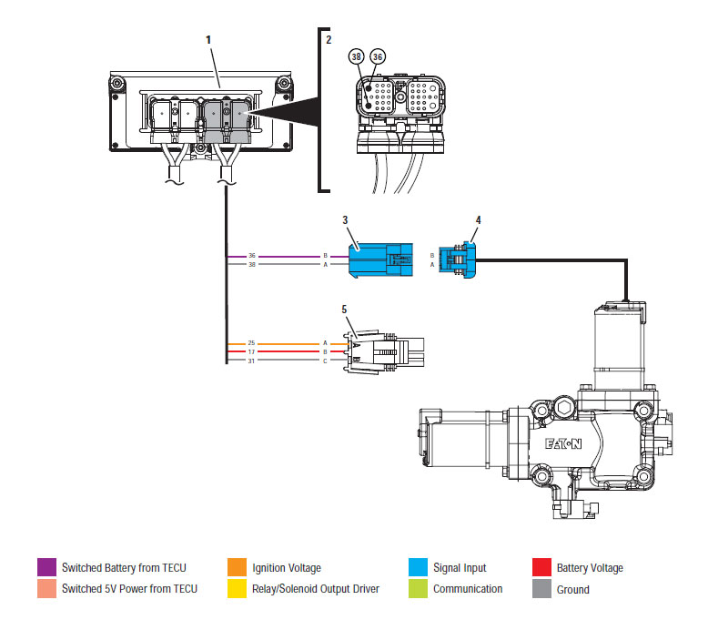
コンポーネントの識別:

[/fusion_text][/fusion_builder_column][fusion_builder_column type=”1_1layout=”1_2spacing=”” center_content=nolink=”” target=_selfmin_height=”” hide_on_mobile=small-visibility,medium-visibility,large-visibilityclass=”” id=”” background_color=”” background_image=”” background_image_id=”” background_position=left topbackground_repeat=no-repeathover_type=noneborder_size=”0″ border_color=”” border_style=solidborder_position=allpadding_top=”” padding_right=”” padding_bottom=”” padding_left=”” margin_top=”” margin_bottom=”” animation_type=”” animation_direction=leftanimation_speed=”0.3″ animation_offset=”” last=no”][fusion_imageframe image_id=”14356|fullmax_width=”” style_type=”” blur=”” stylecolor=”” hover_type=nonebordersize=”” bordercolor=”” borderradius=”” align=centerlightbox=yesgallery_id=”” lightbox_image=https://www.globaltransmissionsupply.com/wp-content/uploads/Gear-motor-circuit-fault-component-identification.jpglightbox_image_id=”14356|fullalt=”歯車モータ回路の故障コンポーネント識別イートンフラー送信” link=”” linktarget=_selfhide_on_mobile=small-visibility,medium-visibility,large-visibilityclass=”” id=”” animation_type=”” animation_direction=leftanimation_speed=”0.3″ animation_offset=””]https://www.globaltransmissionsupply.com/wp-content/uploads/Gear-motor-circuit-fault-component-identification.jpg[/fusion_imageframe][fusion_text columns=”2″ column_min_width=”” column_spacing=”” rule_style=defaultrule_size=”” rule_color=”” hide_on_mobile=small-visibility,medium-visibility,large-visibilityclass=”” id=””]

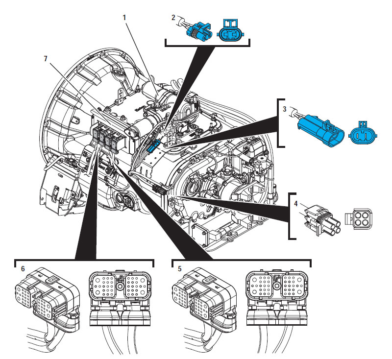
1. X-Yシフター
2. 2-ウェイギアモーターコネクター (青)
3. 2-ウェイギアモーターコネクタ本体 (青)
4. 4-ウェイ診断コネクター
5. 38-ウェイトランスミッションハーネスコネクタ
6. 38-道車両ハーネスコネクタ
7. トランスミッション電子制御ユニット (TECU)

[/fusion_text][/fusion_builder_column][fusion_builder_column type=”1_1layout=”1_1spacing=”” center_content=nolink=”” target=_selfmin_height=”” hide_on_mobile=small-visibility,medium-visibility,large-visibilityclass=”” id=”” background_image_id=”” background_color=”#000000″ background_image=”” background_position=left topundefined=”” background_repeat=no-repeathover_type=noneborder_size=”0″ border_color=”” border_style=solidborder_position=allpadding_top=”” padding_right=”” padding_bottom=”” padding_left=”” margin_top=”20″ margin_bottom=”20″ animation_type=”” animation_direction=leftanimation_speed=”0.3″ animation_offset=”” last=no”][fusion_text columns=”” column_min_width=”” column_spacing=”” rule_style=defaultrule_size=”” rule_color=”” hide_on_mobile=small-visibility,medium-visibility,large-visibilityclass=”” id=””]

注意: を参照してください。 イートンハイブリッドコンポーネントおよびコネクタの位置 MY09システムでのコネクタの位置については、.
[/fusion_text][/fusion_builder_column][fusion_builder_column type=”1_1layout=”1_1spacing=”” center_content=nolink=”” target=_selfmin_height=”” hide_on_mobile=small-visibility,medium-visibility,large-visibilityclass=”” id=”” background_color=”” background_image=”” background_image_id=”” background_position=left topbackground_repeat=no-repeathover_type=noneborder_size=”0″ border_color=”” border_style=solidborder_position=allpadding_top=”” padding_right=”” padding_bottom=”” padding_left=”” margin_top=”” margin_bottom=”” animation_type=”” animation_direction=leftanimation_speed=”0.3″ animation_offset=”” last=no”][fusion_imageframe image_id=”14360|fullmax_width=”” style_type=”” blur=”” stylecolor=”” hover_type=nonebordersize=”” bordercolor=”” borderradius=”” align=centerlightbox=yesgallery_id=”” lightbox_image=https://www.globaltransmissionsupply.com/wp-content/uploads/TECU-rail-motor-connector-locations.jpglightbox_image_id=”14320|fullalt=”歯車モータ回路の故障のトラブルシューティングのためのTECU場所” link=”” linktarget=_selfhide_on_mobile=small-visibility,medium-visibility,large-visibilityclass=”” id=”” animation_type=”” animation_direction=leftanimation_speed=”0.3″ animation_offset=””]https://www.globaltransmissionsupply.com/wp-content/uploads/TECU-location.jpg[/fusion_imageframe][/fusion_builder_column][/fusion_builder_row][/fusion_builder_container][fusion_builder_container hundred_percent=nohundred_percent_height=nohundred_percent_height_scroll=nohundred_percent_height_center_content=yesequal_height_columns=nomenu_anchor=”” hide_on_mobile=small-visibility,medium-visibility,large-visibilitystatus=publishedpublish_date=”” class=”” id=”” background_color=”” background_image=”” background_position=center centerbackground_repeat=no-repeatfade=nobackground_parallax=noneenable_mobile=noparallax_speed=”0.3″ video_mp4=”” video_webm=”” video_ogv=”” video_url=”” video_aspect_ratio=”16:9″ video_loop=yesvideo_mute=yesvideo_preview_image=”” border_size=”” border_color=”” border_style=solidmargin_top=”” margin_bottom=”” padding_top=”” padding_right=”” padding_bottom=”” padding_left=””][fusion_builder_row][fusion_builder_column type=”1_1layout=”1_1spacing=”” center_content=nolink=”” target=_selfmin_height=”” hide_on_mobile=small-visibility,medium-visibility,large-visibilityclass=”” id=”” background_color=”” background_image=”” background_image_id=”” background_position=left topbackground_repeat=no-repeathover_type=noneborder_size=”0″ border_color=”” border_style=solidborder_position=allpadding_top=”” padding_right=”” padding_bottom=”” padding_left=”” margin_top=”” margin_bottom=”” animation_type=”” animation_direction=leftanimation_speed=”0.3″ animation_offset=”” last=no”][fusion_modal name=warnings_cautionstitle=”警告 & 注意事項” size=largebackground=”” border_color=”” show_footer=yesclass=”” id=””]危険: 危険は指示された手順に従わない場合は、重傷を負ったり殺されることを示します.
警告: 警告は、すぐに危険を示し、, あなたが示された手順に従わない場合には重大な人身事故につながる可能性があります.
あぶない: 注意は、あなたが示された手順に従わない場合は車両や物的損害が発生する可能性を示しています.

注意: 注コンポーネント/システムの診断又は修理に役立つ追加の詳細を示しています.

人身事故を避けるために、指示された順序で指定された手順に従ってください:

1. 高電圧コーンは、車両の周囲にあり、ロックアウトは、PECにインストールされている場合, 車両を発進させるべきである唯一の人はロックアウトタグに署名した人物であります.
2. 車両の作業やタクシーを出る前に、エンジンが実行されている間, あなたは、パーキングブレーキを設定し、「N」にシフトレバーを配置する必要があります, そして、車輪をブロックします.
3. 安全対策のため, 常に「N.」からギアポジションを選択する前に、サービスブレーキを従事
4. 必ず運転席に着席する車両を開始する前に, シフト制御の「N」を選択, そして、パーキングブレーキを設定.
5. EPTO付き車両で, エンジンおよび/または
モータ/発電機はEPTOモードで起動することができます. 車両のメンテナンスや作業を行うことはありません, このモード中.
6. 12-ボルトバッテリー正 (+) そして、負 (-) 任意のハイブリッド車両搭載上の任意の溶接前に切断されなければなりません.

あぶない: 機器の故障や破損を避けるために、指示された順序で指定された手順に従ってください.
あぶない: 空気圧が適正なレベルになるまで、パーキングブレーキを解除したり、ギアを選択しようとしないでください.
あぶない: 「N」にシフトレバーを場所を牽引時の伝送への損傷を避け、地面から駆動輪を持ち上げたり、ドライブラインを切断するには.

高電圧の警告 & 注意事項

  • CO2を使用するか、またはドライケミカル消火器.
  • 高電圧配線はオレンジ絶縁または複雑なチューブで覆われており、コネクタの警告ラベルが付いています.
  • すべてのEaton®ハイブリッドディーゼル/電気自動車は、「ハイブリッドマークされます’ 車両の外側に, ダッシュ上のシフトラベルと一緒に.
  • シャーシ搭載ハイブリッド部品の特定の場所のためにOEMを参照.
  • オレンジ色の高電圧ケーブルに切断しないでください.
  • PECをにカットしたり開いたりしないでください.
  • カットまたはDC / DCコンバータを開けないでください.
  • カットまたはインバータを開けないでください.

バッファゾーンを設定し、高電圧絶縁ゴム手袋されなければなりません (クラス 0 革プロテクター付き) 高電圧で作業する前に必要とされています. これらの指示に従わないと、重大な人身事故や死に至ることが.
高電圧システムで作業しながら、着用しなければならないゴム絶縁手袋はクラスであります 0 革プロテクター付き. ゴム手袋は、ページの「診断ツール/サービス出版物」で見つかったゴム製絶縁手袋の試験手順以下のEVERY使用する前にテストする必要があります 6. これらの指示に従わないと、重大な人身事故や死に至ることが.
ページの「高電圧サービスのシャットダウンとパワーアップ手順」を検査または任意の高電圧ケーブルやコンポーネントの作業を行う前に、 4 従うべきです. これらの指示に従わないと、重大な人身事故や死に至ることが.
ロックアウトとタグアウト装置は、車両にロックアウトとタグアウト装置を配置技術によって除去されなければなりません. これらの指示に従わないと、重大な人身事故や死に至ることが.
高電圧絶縁ゴム手袋 (クラス 0 革プロテクター付き) 任意の上で作業するときに着用しなければなりません
高電圧ケーブル. ページの「高電圧・サービスのシャットダウンとパワーアップ手順」 4 任意の高電圧ケーブルを除去する前に従わなければなりません. これらの指示に従わないと、重大な人身事故や死に至ることが.
高電圧ケーブルや配線がオレンジ色であり、コネクタの警告ラベルが含まれています. 高電圧部品は、ラベルが付いています. 高電圧絶縁ゴム手袋 (クラス 0 革プロテクター付き) これらのコンポーネントのいずれかで作業するときに使用する必要があります. これらの指示に従わないと、重大な人身事故や死に至ることが.

高電圧・サービスのシャットダウン手順

高電圧サービスのシャットダウンとパワーアップ手順1. 「高電圧ワークエリア」の手順に従ってください.
2. PECの前面にある赤いPECサービススイッチの位置を確認し、オフにプッシュします.
3. サービススイッチのカバーを外し、ロックアウトブラケットを取り付けます (J48506).
4. ロックアウトブラケットにタグを固定し.
5. PECサービススイッチがオフの位置から移動することはできません確認してください.
6. システムは最低に設定することを許可します 5 高電圧を放電する分.
7. ServiceRangerを接続し、データモニタPIDを表示 116 「高電圧バッテリポテンシャル」と呼ば使用SPN 520323 J1939接続用の「バッテリー電圧RB」 (リレーボックス).
8. 電圧はする必要があります 30 ボルト以下. 電圧は、上記の場合 30 ボルト, 車両に取り組み、1-800-826-HELPでEaton®接触していません (4357).
9. イグニッションキーをオフにし、修理やトラブルシューティングのステップに進みます.
注意: キーがオフのときの電圧がゼロに低下します.

高電圧サービスパワーアップ手順

1. 彼らのロックされた位置にすべての高電圧コネクタをインストールします。.
2. あなたがいる場合は人が車両に取り組んで, ロックアウトブラケットとタグを削除.
3. サービススイッチ上でロックアウトブラケットを再インストールします.
4. サービスを引っ張り出し切り替えて、車両がために設定しましょう 2 分.
5. Start vehicle when appropriate.[/fusion_modal][fusion_modal name=component_locationtitle=”イートンハイブリッドコンポーネントおよびコネクタの位置 ” size=largebackground=”#ffffffborder_color=”” show_footer=yesclass=”” id=””]

イートンハイブリッドコンポーネントおよびコネクタの位置MY08システム

[/fusion_modal][fusion_modal name=component_location2title=”イートンハイブリッドコンポーネントおよびコネクタの位置MY09システム” size=largebackground=”#ffffffborder_color=”” show_footer=yesclass=”” id=””]

イートンハイブリッドコンポーネントおよびコネクタの位置MY09システム

[/fusion_modal][/fusion_builder_column][/fusion_builder_row][/fusion_builder_container][fusion_builder_container hundred_percent=nohundred_percent_height=nohundred_percent_height_scroll=nohundred_percent_height_center_content=yesequal_height_columns=nomenu_anchor=”” hide_on_mobile=small-visibility,medium-visibility,large-visibilitystatus=publishedpublish_date=”” class=”” id=”” background_color=”” background_image=”” background_position=center centerbackground_repeat=no-repeatfade=nobackground_parallax=noneenable_mobile=noparallax_speed=”0.3″ video_mp4=”” video_webm=”” video_ogv=”” video_url=”” video_aspect_ratio=”16:9″ video_loop=yesvideo_mute=yesvideo_preview_image=”” border_size=”” border_color=”” border_style=solidmargin_top=”” margin_bottom=”” padding_top=”” padding_right=”” padding_bottom=”” padding_left=””][fusion_builder_row][fusion_builder_column type=”1_1layout=”1_1spacing=”” center_content=nolink=”” target=_selfmin_height=”” hide_on_mobile=small-visibility,medium-visibility,large-visibilityclass=”” id=”” background_color=”” background_image=”” background_image_id=”” background_position=left topbackground_repeat=no-repeathover_type=noneborder_size=”0″ border_color=”” border_style=solidborder_position=allpadding_top=”” padding_right=”” padding_bottom=”” padding_left=”” margin_top=”” margin_bottom=”” animation_type=”” animation_direction=leftanimation_speed=”0.3″ animation_offset=”” last=no”][fusion_content_boxes layout=clean-horizontalcolumns=”1″ title_size=”18pxheading_size=”3″ title_color=”#ffffffbody_color=”#ffffffbackgroundcolor=”#4f4f4ficon=”” iconflip=”” iconrotate=”” iconspin=noiconcolor=”” icon_circle=”” icon_circle_radius=”” circlecolor=”” circlebordersize=”” circlebordercolor=”” outercirclebordersize=”” outercirclebordercolor=”” icon_size=”” icon_hover_type=”” hover_accent_color=”” image=”” image_id=”” image_width=”” image_height=”” link_type=”” button_span=”” link_area=”” link_target=”” icon_align=leftanimation_type=”” animation_delay=”” animation_offset=”” animation_direction=leftanimation_speed=”0.3″ margin_top=”” margin_bottom=”” hide_on_mobile=small-visibility,medium-visibility,large-visibilityclass=”” id=””][fusion_content_box title=STEP 1. アクティブまたは非アクティブ故障コードをチェック.backgroundcolor=”” icon=”” iconflip=”” iconrotate=”” iconspin=noiconcolor=”” circlecolor=”” circlebordersize=”” circlebordercolor=”” outercirclebordersize=”” outercirclebordercolor=”” image=”” image_id=”” image_width=”” image_height=”” link=”” linktext=”続きを読む” link_target=”” animation_type=”” animation_direction=leftanimation_speed=”0.3″ animation_offset=””]

  1. エンジンをオフにした状態で上キー.
  2. 接続ServiceRanger.
  3. ServiceRanger内のサービス活動レポートを作成することにより、スナップショットやVPAのデータを取得します.
  4. 利用可能な最新レベルに更新伝送ソフトウェア.
    あぶない: TECUの損傷を避けるために、, イートン・承認された通信アダプタを使用してソフトウェアを更新する前に、すべての衛星システムが無効になっていることを確認.
  5. トランスミッション故障コードとFMISを取得し、記録, そして彼らの出現とタイムスタンプ.
    • いずれかの場合はフォルトコード 33 若しくは 34 アクティブです, 最初のフォルトコードの分離手順に従って、それをトラブルシューティング.
    • フォルトコードの場合 61 アクティブで、フォルトコード 33 またはフォルトコード 34 ある非アクティブまたは設定されていません, 進みます 4.
    • フォルトコードの場合 61 非アクティブであり、 コードの障害 33 若しくは コードの障害 34 ある非アクティブまたは設定されていません, 進みます 2.

[/fusion_content_box][/fusion_content_boxes][fusion_content_boxes layout=clean-horizontalcolumns=”1″ title_size=”18pxheading_size=”3″ title_color=”#ffffffbody_color=”#ffffffbackgroundcolor=”#4f4f4ficon=”” iconflip=”” iconrotate=”” iconspin=noiconcolor=”” icon_circle=”” icon_circle_radius=”” circlecolor=”” circlebordersize=”” circlebordercolor=”” outercirclebordersize=”” outercirclebordercolor=”” icon_size=”” icon_hover_type=”” hover_accent_color=”” image=”” image_id=”” image_width=”” image_height=”” link_type=”” button_span=”” link_area=”” link_target=”” icon_align=leftanimation_type=”” animation_delay=”” animation_offset=”” animation_direction=leftanimation_speed=”0.3″ margin_top=”” margin_bottom=”” hide_on_mobile=small-visibility,medium-visibility,large-visibilityclass=”” id=””][fusion_content_box title=STEP 2. 電源とグラウンド電源の状態を確認してください. backgroundcolor=”” icon=”” iconflip=”” iconrotate=”” iconspin=noiconcolor=”” circlecolor=”” circlebordersize=”” circlebordercolor=”” outercirclebordersize=”” outercirclebordercolor=”” image=”” image_id=”” image_width=”” image_height=”” link=”” linktext=”続きを読む” link_target=”” animation_type=”” animation_direction=leftanimation_speed=”0.3″ animation_offset=””]

  1. 電気プリテストGen1のECAを実行します. 読書を記録します(S) ステップロードテストから 3 電気プリテストの.
    • 電気プレテストが失敗した場合、, 電気プレテストの指示に従って修理. 再テスト車両の運転.
    • 電気プレテストは合格した場合, 進みます 3.

[/fusion_content_box][/fusion_content_boxes][fusion_content_boxes layout=clean-horizontalcolumns=”1″ title_size=”18pxheading_size=”3″ title_color=”#ffffffbody_color=”#ffffffbackgroundcolor=”#4f4f4ficon=”” iconflip=”” iconrotate=”” iconspin=noiconcolor=”” icon_circle=”” icon_circle_radius=”” circlecolor=”” circlebordersize=”” circlebordercolor=”” outercirclebordersize=”” outercirclebordercolor=”” icon_size=”” icon_hover_type=”” hover_accent_color=”” image=”” image_id=”” image_width=”” image_height=”” link_type=”” button_span=”” link_area=”” link_target=”” icon_align=leftanimation_type=”” animation_delay=”” animation_offset=”” animation_direction=leftanimation_speed=”0.3″ margin_top=”” margin_bottom=”” hide_on_mobile=small-visibility,medium-visibility,large-visibilityclass=”” id=””][fusion_content_box title=STEP 3. 製品の診断を使用します (PD) 断続的な障害を見つけるためのモード.backgroundcolor=”” icon=”” iconflip=”” iconrotate=”” iconspin=noiconcolor=”” circlecolor=”” circlebordersize=”” circlebordercolor=”” outercirclebordersize=”” outercirclebordercolor=”” image=”” image_id=”” image_width=”” image_height=”” link=”” linktext=”続きを読む” link_target=”” animation_type=”” animation_direction=leftanimation_speed=”0.3″ animation_offset=””]

  1. パーキングブレーキとホイールぎっしり.
  2. PDにおける場所送信 (製品の診断) モード.
  3. ウィグルの配線との間の接続 38- TECUと車両バッテリ電源で道車両ハーネスコネクタ. 摩擦や摩擦の兆候を探してください.
  4. ウィグル配線とTECUと黒の38ウェイ伝送ハーネスコネクタの間の接続 (X-レールモーター) 2-ウェイトランスミッションハーネスコネクタ.
  5. ウィグル配線とTECUおよび青の38ウェイコネクタとの間の接続 (Y-ギアモーター) 2- ウェイトランスミッションハーネスコネクタ.
  6. 電源を切ることによって終了PDモード.
    重要: TECU 2-3分は、先に進む前に、完全なパワーダウン・シーケンスを形成するごとに許可します.

    • 車両ハーネスをウィグリングしながら、任意の断層がアクティブに設定した場合, OEM配線の修理または交換のためのOEMのガイドラインを参照してください。. ステップに進みます。 13.
    • 伝送ハーネスをウィグリングしながら、すべての障害がアクティブに設定した場合, トランスミッションハーネスを交換します. ステップに進みます。 13.
    • どちらかのハーネスをウィグリングしながら、何の障害は、Active設定されていない場合, 進みます 4.

[/fusion_content_box][/fusion_content_boxes][fusion_content_boxes layout=clean-horizontalcolumns=”1″ title_size=”18pxheading_size=”3″ title_color=”#ffffffbody_color=”#ffffffbackgroundcolor=”#4f4f4ficon=”” iconflip=”” iconrotate=”” iconspin=noiconcolor=”” icon_circle=”” icon_circle_radius=”” circlecolor=”” circlebordersize=”” circlebordercolor=”” outercirclebordersize=”” outercirclebordercolor=”” icon_size=”” icon_hover_type=”” hover_accent_color=”” image=”” image_id=”” image_width=”” image_height=”” link_type=”” button_span=”” link_area=”” link_target=”” icon_align=leftanimation_type=”” animation_delay=”” animation_offset=”” animation_direction=leftanimation_speed=”0.3″ margin_top=”” margin_bottom=”” hide_on_mobile=small-visibility,medium-visibility,large-visibilityclass=”” id=””][fusion_content_box title=STEP 4. これFMIのセットを確認してください.backgroundcolor=”” icon=”” iconflip=”” iconrotate=”” iconspin=noiconcolor=”” circlecolor=”” circlebordersize=”” circlebordercolor=”” outercirclebordersize=”” outercirclebordercolor=”” image=”” image_id=”” image_width=”” image_height=”” link=”” linktext=”続きを読む” link_target=”” animation_type=”” animation_direction=leftanimation_speed=”0.3″ animation_offset=””]

  1. FMIは、フォルトコードに設定しているかを決定 63.
    • FMIの場合 1 若しくは 12 セット, 進みます 5.
    • FMIの場合 5 設定およびアクティブであります, 進みます 5.
    • FMIの場合 5 セットと非アクティブであります, 進みます 11.
    • FMIの場合 6 セット, TECUを交換. ステップに進みます。 13.

[/fusion_content_box][/fusion_content_boxes][fusion_content_boxes layout=clean-horizontalcolumns=”1″ title_size=”18pxheading_size=”3″ title_color=”#ffffffbody_color=”#ffffffbackgroundcolor=”#4f4f4ficon=”” iconflip=”” iconrotate=”” iconspin=noiconcolor=”” icon_circle=”” icon_circle_radius=”” circlecolor=”” circlebordersize=”” circlebordercolor=”” outercirclebordersize=”” outercirclebordercolor=”” icon_size=”” icon_hover_type=”” hover_accent_color=”” image=”” image_id=”” image_width=”” image_height=”” link_type=”” button_span=”” link_area=”” link_target=”” icon_align=leftanimation_type=”” animation_delay=”” animation_offset=”” animation_direction=leftanimation_speed=”0.3″ margin_top=”” margin_bottom=”” hide_on_mobile=small-visibility,medium-visibility,large-visibilityclass=”” id=””][fusion_content_box title=STEP 5. トランスミッションハーネスとギアモーターを通じて適切な抵抗値を確認します.backgroundcolor=”” icon=”” iconflip=”” iconrotate=”” iconspin=noiconcolor=”” circlecolor=”” circlebordersize=”” circlebordercolor=”” outercirclebordersize=”” outercirclebordercolor=”” image=”” image_id=”” image_width=”” image_height=”” link=”” linktext=”続きを読む” link_target=”” animation_type=”” animation_direction=leftanimation_speed=”0.3″ animation_offset=””]

  1. キーオフ.
  2. TECUから38ウェイトランスミッションハーネスコネクタを外してください.
  3. 38ウェイコネクタが腐食から自由であることを確認します; 端子が曲がっていません, スプレッド, または緩い端末; そして、コネクタ本体に損傷はありません.
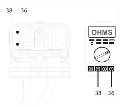
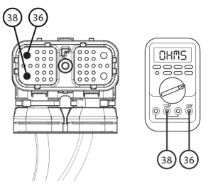
  4. 38ウェイコネクタピン間の抵抗を測定します 36 そして、ピン 38. レコードの読み取り(S).38 極コネクタ
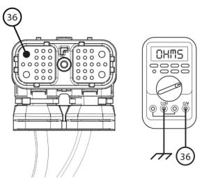
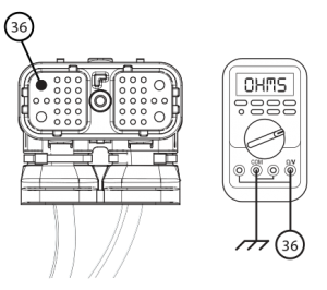
  5. 38ウェイコネクタピン間の抵抗を測定します 36 そして、地面. レコードの読み取り(S).メジャー・ギアモータ抵抗イートンフラー送信
  6. 読書の比較(S) 指定された範囲に:
    • 読書の場合(S) 範囲にあり、, 進みます 6.
    • 読書の場合(S) 範囲外にあります, 進みます 8.

[/fusion_content_box][/fusion_content_boxes][fusion_content_boxes layout=clean-horizontalcolumns=”1″ title_size=”18pxheading_size=”3″ title_color=”#ffffffbody_color=”#ffffffbackgroundcolor=”#4f4f4ficon=”” iconflip=”” iconrotate=”” iconspin=noiconcolor=”” icon_circle=”” icon_circle_radius=”” circlecolor=”” circlebordersize=”” circlebordercolor=”” outercirclebordersize=”” outercirclebordercolor=”” icon_size=”” icon_hover_type=”” hover_accent_color=”” image=”” image_id=”” image_width=”” image_height=”” link_type=”” button_span=”” link_area=”” link_target=”” icon_align=leftanimation_type=”” animation_delay=”” animation_offset=”” animation_direction=leftanimation_speed=”0.3″ margin_top=”” margin_bottom=”” hide_on_mobile=small-visibility,medium-visibility,large-visibilityclass=”” id=””][fusion_content_box title=STEP 6. これFMIのセットを確認してください.backgroundcolor=”” icon=”” iconflip=”” iconrotate=”” iconspin=noiconcolor=”” circlecolor=”” circlebordersize=”” circlebordercolor=”” outercirclebordersize=”” outercirclebordercolor=”” image=”” image_id=”” image_width=”” image_height=”” link=”” linktext=”続きを読む” link_target=”” animation_type=”” animation_direction=leftanimation_speed=”0.3″ animation_offset=””]

  1. FMIは、フォルトコードに設定しているかを決定 63.
    • FMIの場合 1 セット, X-Yシフターと伝送ハーネスを交換します. ステップに進みます。 13.
    • FMIの場合 5 セット, 進みます 7.
    • FMIの場合 12 セット, 進みます 8.

[/fusion_content_box][/fusion_content_boxes][fusion_content_boxes layout=clean-horizontalcolumns=”1″ title_size=”18pxheading_size=”3″ title_color=”#ffffffbody_color=”#ffffffbackgroundcolor=”#4f4f4ficon=”” iconflip=”” iconrotate=”” iconspin=noiconcolor=”” icon_circle=”” icon_circle_radius=”” circlecolor=”” circlebordersize=”” circlebordercolor=”” outercirclebordersize=”” outercirclebordercolor=”” icon_size=”” icon_hover_type=”” hover_accent_color=”” image=”” image_id=”” image_width=”” image_height=”” link_type=”” button_span=”” link_area=”” link_target=”” icon_align=leftanimation_type=”” animation_delay=”” animation_offset=”” animation_direction=leftanimation_speed=”0.3″ margin_top=”” margin_bottom=”” hide_on_mobile=small-visibility,medium-visibility,large-visibilityclass=”” id=””][fusion_content_box title=STEP 7. TECUの内部回路の抵抗を確認.backgroundcolor=”” icon=”” iconflip=”” iconrotate=”” iconspin=noiconcolor=”” circlecolor=”” circlebordersize=”” circlebordercolor=”” outercirclebordersize=”” outercirclebordercolor=”” image=”” image_id=”” image_width=”” image_height=”” link=”” linktext=”続きを読む” link_target=”” animation_type=”” animation_direction=leftanimation_speed=”0.3″ animation_offset=””]

  1. TECUへの再接続38ウェイトランスミッションハーネス.
  2. トランスミッションハーネスから外しブルー2ウェイギアモーターコネクター.
  3. 4ウェイの診断コネクタのコネクタカバーを取り外します.
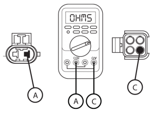
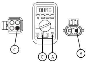
  4. 2ウェイコネクタピンA及び4ウェイコネクタピンCとの間の抵抗を測定します. レコードの読み取り(S).38 TECUへの道伝送ハーネス
  5. 逆メーターリードと2ウェイコネクタピンA及び4ウェイコネクタピンCとの間の同一の測定を行います. レコードの読み取り(S).イートンフラー 38 TECUへの道伝送ハーネス
  6. 読書の比較(S) 録音中に指定された範囲に.
    • 読書の場合(S) 範囲にあり、, X-Yシフターを交換. ステップに進みます。 13.
    • 読書の場合(S) 範囲外にあります, TECUを交換. ステップに進みます。 13.

[/fusion_content_box][/fusion_content_boxes][fusion_content_boxes layout=clean-horizontalcolumns=”1″ title_size=”18pxheading_size=”3″ title_color=”#ffffffbody_color=”#ffffffbackgroundcolor=”#4f4f4ficon=”” iconflip=”” iconrotate=”” iconspin=noiconcolor=”” icon_circle=”” icon_circle_radius=”” circlecolor=”” circlebordersize=”” circlebordercolor=”” outercirclebordersize=”” outercirclebordercolor=”” icon_size=”” icon_hover_type=”” hover_accent_color=”” image=”” image_id=”” image_width=”” image_height=”” link_type=”” button_span=”” link_area=”” link_target=”” icon_align=leftanimation_type=”” animation_delay=”” animation_offset=”” animation_direction=leftanimation_speed=”0.3″ margin_top=”” margin_bottom=”” hide_on_mobile=small-visibility,medium-visibility,large-visibilityclass=”” id=””][fusion_content_box title=STEP 8. X-Yギアモーターの抵抗を確認し、モータがグランドに短絡されていないベリファイ.backgroundcolor=”” icon=”” iconflip=”” iconrotate=”” iconspin=noiconcolor=”” circlecolor=”” circlebordersize=”” circlebordercolor=”” outercirclebordersize=”” outercirclebordercolor=”” image=”” image_id=”” image_width=”” image_height=”” link=”” linktext=”続きを読む” link_target=”” animation_type=”” animation_direction=leftanimation_speed=”0.3″ animation_offset=””]

  1. キーオフ.
  2. トランスミッションハーネスから外しブルー2ウェイギアモーターコネクター.
  3. 2ウェイコネクタは、任意の腐食から自由であることを確認; 端子が曲がっていません, スプレッドまたは緩いです, そして、コネクタ本体に損傷はありません.
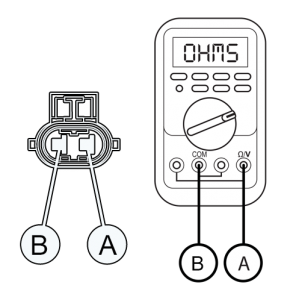
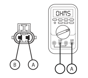
  4. 2ウェイコネクタ端子Aと端子Bとの間の抵抗を測定します. レコードの読み取り(S).2-ウェイギアモーターコネクター
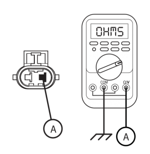
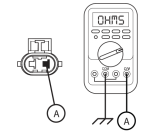
  5. 2ウェイコネクタ端子Aと接地との間の測定抵抗. レコードの読み取り.2 極コネクタ
  6. 読書の比較(S) 指定された範囲に.
    • 読書の場合(S) 範囲にあり、, 進みます 9.
    • 読書の場合(S) 範囲外にあります, X-Yシフターを交換. ステップに進みます。 13.

[/fusion_content_box][/fusion_content_boxes][fusion_content_boxes layout=clean-horizontalcolumns=”1″ title_size=”18pxheading_size=”3″ title_color=”#ffffffbody_color=”#ffffffbackgroundcolor=”#4f4f4ficon=”” iconflip=”” iconrotate=”” iconspin=noiconcolor=”” icon_circle=”” icon_circle_radius=”” circlecolor=”” circlebordersize=”” circlebordercolor=”” outercirclebordersize=”” outercirclebordercolor=”” icon_size=”” icon_hover_type=”” hover_accent_color=”” image=”” image_id=”” image_width=”” image_height=”” link_type=”” button_span=”” link_area=”” link_target=”” icon_align=leftanimation_type=”” animation_delay=”” animation_offset=”” animation_direction=leftanimation_speed=”0.3″ margin_top=”” margin_bottom=”” hide_on_mobile=small-visibility,medium-visibility,large-visibilityclass=”” id=””][fusion_content_box title=STEP 9. これFMIのセットを確認してください.backgroundcolor=”” icon=”” iconflip=”” iconrotate=”” iconspin=noiconcolor=”” circlecolor=”” circlebordersize=”” circlebordercolor=”” outercirclebordersize=”” outercirclebordercolor=”” image=”” image_id=”” image_width=”” image_height=”” link=”” linktext=”続きを読む” link_target=”” animation_type=”” animation_direction=leftanimation_speed=”0.3″ animation_offset=””]

  1. FMIは、フォルトコードに設定しているかを決定 63.
    • FMIの場合 1 セット, トランスミッションハーネスを交換します. ステップに進みます。 13.
    • FMIの場合 5 セット, トランスミッションハーネスを交換します. ステップに進みます。 13.
    • FMIの場合 12 セット, 進みます 10.

[/fusion_content_box][/fusion_content_boxes][fusion_content_boxes layout=clean-horizontalcolumns=”1″ title_size=”18pxheading_size=”3″ title_color=”#ffffffbody_color=”#ffffffbackgroundcolor=”#4f4f4ficon=”” iconflip=”” iconrotate=”” iconspin=noiconcolor=”” icon_circle=”” icon_circle_radius=”” circlecolor=”” circlebordersize=”” circlebordercolor=”” outercirclebordersize=”” outercirclebordercolor=”” icon_size=”” icon_hover_type=”” hover_accent_color=”” image=”” image_id=”” image_width=”” image_height=”” link_type=”” button_span=”” link_area=”” link_target=”” icon_align=leftanimation_type=”” animation_delay=”” animation_offset=”” animation_direction=leftanimation_speed=”0.3″ margin_top=”” margin_bottom=”” hide_on_mobile=small-visibility,medium-visibility,large-visibilityclass=”” id=””][fusion_content_box title=STEP 10. 負荷TECUに車両電源をテスト.backgroundcolor=”” icon=”” iconflip=”” iconrotate=”” iconspin=noiconcolor=”” circlecolor=”” circlebordersize=”” circlebordercolor=”” outercirclebordersize=”” outercirclebordercolor=”” image=”” image_id=”” image_width=”” image_height=”” link=”” linktext=”続きを読む” link_target=”” animation_type=”” animation_direction=leftanimation_speed=”0.3″ animation_offset=””]

  1. キーオフ.
  2. 車両ハーネスからTECUバッテリ電源及び接地供給を確認し、適切に接続され、腐食されません, 損傷を受けました, または緩いです.
  3. TECUで38ウェイ車両ハーネスコネクタを外してください.
  4. 38ウェイコネクタが腐食から自由であることを確認します, 何曲がっはありません, スプレッド, または緩い端末, そして、コネクタ本体に損傷はありません.
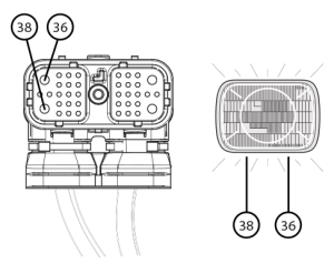
  5. 負荷試験外部負荷源を有する車両用電源ハーネス. ピンに取り付けられたシールドビームヘッドランプ又はブロワモーターを使用 36 (パワー) そして、ピン 38 (接地). 以下のためのロードテスト 5 ハーネスを確認する分には、インストールされ、30アンペアのヒューズと負荷を運ぶでしょう.TECU
  6. ウィグル車両のバッテリーからTECUへの負荷テスト中にハーネス.
    • 問題は、車両ハーネスやコネクタで発見された場合, OEM配線の修理または交換のためのOEMのガイドラインを参照し、負荷テストを継続.
    • 車両ハーネスは、負荷を運ぶしない場合, OEM配線の修理または交換のためのOEMのガイドラインを参照してください。. ステップに進みます。 13.
    • 何の問題は、車両ハーネスやコネクタと電源で見つからない場合は、負荷を運びます, TECUを交換. ステップに進みます。 13.

[/fusion_content_box][/fusion_content_boxes][fusion_content_boxes layout=clean-horizontalcolumns=”1″ title_size=”18pxheading_size=”3″ title_color=”#ffffffbody_color=”#ffffffbackgroundcolor=”#4f4f4ficon=”” iconflip=”” iconrotate=”” iconspin=noiconcolor=”” icon_circle=”” icon_circle_radius=”” circlecolor=”” circlebordersize=”” circlebordercolor=”” outercirclebordersize=”” outercirclebordercolor=”” icon_size=”” icon_hover_type=”” hover_accent_color=”” image=”” image_id=”” image_width=”” image_height=”” link_type=”” button_span=”” link_area=”” link_target=”” icon_align=leftanimation_type=”” animation_delay=”” animation_offset=”” animation_direction=leftanimation_speed=”0.3″ margin_top=”” margin_bottom=”” hide_on_mobile=small-visibility,medium-visibility,large-visibilityclass=”” id=””][fusion_content_box title=STEP 11. トランスミッションハーネスとギアモーターを通じて適切な抵抗値を確認します.backgroundcolor=”” icon=”” iconflip=”” iconrotate=”” iconspin=noiconcolor=”” circlecolor=”” circlebordersize=”” circlebordercolor=”” outercirclebordersize=”” outercirclebordercolor=”” image=”” image_id=”” image_width=”” image_height=”” link=”” linktext=”続きを読む” link_target=”” animation_type=”” animation_direction=leftanimation_speed=”0.3″ animation_offset=””]

  1. キーオフ.
  2. TECUから38ウェイトランスミッションハーネスコネクタを外してください.
  3. 38ウェイコネクタが腐食から自由であることを確認します, 何曲がっはありません, スプレッド, または緩い端末, そして、コネクタ本体に損傷はありません.
  4. 38ウェイコネクタピン間の抵抗を測定します 36 そして、ピン 38. レコードの読み取り.トランスミッションハーネスとギアモーターイートンフラー伝送を介して適切な抵抗
  5. 38ウェイコネクタピン間の抵抗を測定します 36 そして、地面. レコードの読み取り.抵抗ギアモータイートンフラー透過を測定
  6. 読書の比較(S) テーブル内の指定された範囲に:
    • 読書の場合(S) 範囲にあり、, X-Yシフターを交換. ステップに進みます。 13.
    • 読書の場合(S) 範囲外にあります, 進みます 12.

[/fusion_content_box][/fusion_content_boxes][fusion_content_boxes layout=clean-horizontalcolumns=”1″ title_size=”18pxheading_size=”3″ title_color=”#ffffffbody_color=”#ffffffbackgroundcolor=”#4f4f4ficon=”” iconflip=”” iconrotate=”” iconspin=noiconcolor=”” icon_circle=”” icon_circle_radius=”” circlecolor=”” circlebordersize=”” circlebordercolor=”” outercirclebordersize=”” outercirclebordercolor=”” icon_size=”” icon_hover_type=”” hover_accent_color=”” image=”” image_id=”” image_width=”” image_height=”” link_type=”” button_span=”” link_area=”” link_target=”” icon_align=leftanimation_type=”” animation_delay=”” animation_offset=”” animation_direction=leftanimation_speed=”0.3″ margin_top=”” margin_bottom=”” hide_on_mobile=small-visibility,medium-visibility,large-visibilityclass=”” id=””][fusion_content_box title=STEP 12. X-Yシフタギアモーターの内部抵抗を確認し、モータがグランドに短絡されていないベリファイ.backgroundcolor=”” icon=”” iconflip=”” iconrotate=”” iconspin=noiconcolor=”” circlecolor=”” circlebordersize=”” circlebordercolor=”” outercirclebordersize=”” outercirclebordercolor=”” image=”” image_id=”” image_width=”” image_height=”” link=”” linktext=”続きを読む” link_target=”” animation_type=”” animation_direction=leftanimation_speed=”0.3″ animation_offset=””]

  1. キーオフ.
  2. トランスミッションハーネスから外しブルー2ウェイギアモーターコネクター.
  3. 2ウェイコネクタが腐食から自由であることを確認します, 何曲がっはありません, スプレッド, または緩い端末, そして、コネクタ本体に損傷はありません.
  4. 2ウェイコネクタ端子Aと端子Bとの間の抵抗を測定します. テーブルのレコードの読み取り.シフターギアモーターの地上試験イートンフラー伝送
  5. 2ウェイコネクタ端子Aと接地間の抵抗を測定. レコードの読み取り.歯車モータ抵抗イートンフラー透過を測定
  6. テーブル内の指定された範囲に抵抗を比較.
    • 両方の抵抗値の範囲内にある場合, トランスミッションハーネスを交換します. ステップに進みます。 13.
    • いずれかの抵抗値は、範囲外である場合, Xを交換- Yシフター. ステップに進みます。 13.

[/fusion_content_box][/fusion_content_boxes][fusion_content_boxes layout=clean-horizontalcolumns=”1″ title_size=”18pxheading_size=”3″ title_color=”#ffffffbody_color=”#ffffffbackgroundcolor=”#4f4f4ficon=”” iconflip=”” iconrotate=”” iconspin=noiconcolor=”” icon_circle=”” icon_circle_radius=”” circlecolor=”” circlebordersize=”” circlebordercolor=”” outercirclebordersize=”” outercirclebordercolor=”” icon_size=”” icon_hover_type=”” hover_accent_color=”#f41000image=”” image_id=”” image_width=”” image_height=”” link_type=”” button_span=”” link_area=”” link_target=”” icon_align=leftanimation_type=”” animation_delay=”” animation_offset=”” animation_direction=leftanimation_speed=”0.3″ margin_top=”” margin_bottom=”” hide_on_mobile=small-visibility,medium-visibility,large-visibilityclass=”” id=””][fusion_content_box title=STEP 13. 修復を検査します.backgroundcolor=”” icon=”” iconflip=”” iconrotate=”” iconspin=noiconcolor=”” circlecolor=”” circlebordersize=”” circlebordercolor=”” outercirclebordersize=”” outercirclebordercolor=”” image=”” image_id=”” image_width=”” image_height=”” link=”” linktext=”続きを読む” link_target=”” animation_type=”” animation_direction=leftanimation_speed=”0.3″ animation_offset=””]

  1. キーオフ.
  2. すべてのコネクタとバッテリーのマイナスケーブルを再接続します.
  3. 3. エンジンをオフにした状態で上キー.
  4. クリアコード, 見る クリア非アクティブな障害.
  5. 車を運転して、コードをリセットしたり、問題を再現しようとし.
  6. コードの確認, 見る アクティブおよび非アクティブの障害を表示.
    • いいえコードの場合, テストは完了です.
    • もし、故障コード 63 表示されます, テストでエラーを見つけます, 進みます 1.
    • 以外のコードの場合 63 表示されます, 見る コードインデックスリストフォールト.

[/fusion_content_box][/fusion_content_boxes][/fusion_builder_column][/fusion_builder_row][/fusion_builder_container][fusion_global id=”13788″]