[fusion_builder_container hundred_percent=”no” hundred_percent_height=”no” hundred_percent_height_scroll=”no” hundred_percent_height_center_content=”yes” equal_height_columns=”no” menu_anchor=”” hide_on_mobile=”small-visibility,medium-visibility,large-visibility” status=”published” publish_date=”” class=”” id=”” background_color=”” background_image=”” background_position=”center center” background_repeat=”no-repeat” fade=”no” background_parallax=”none” enable_mobile=”no” parallax_speed=”0.3″ video_mp4=”” video_webm=”” video_ogv=”” video_url=”” video_aspect_ratio=”16:9″ video_loop=”yes” video_mute=”yes” video_preview_image=”” border_size=”” border_color=”” border_style=”solid” margin_top=”35″ margin_bottom=”” padding_top=”” padding_right=”” padding_bottom=”” padding_left=””][fusion_builder_row][fusion_builder_column type=”1_1″ layout=”1_1″ spacing=”” center_content=”no” link=”” target=”_self” min_height=”” hide_on_mobile=”small-visibility,medium-visibility,large-visibility” class=”” id=”” background_color=”” background_image=”” background_image_id=”” background_position=”left top” background_repeat=”no-repeat” hover_type=”none” border_size=”0″ border_color=”” border_style=”solid” border_position=”all” padding_top=”” padding_right=”” padding_bottom=”” padding_left=”” margin_top=”” margin_bottom=”” animation_type=”” animation_direction=”left” animation_speed=”0.3″ animation_offset=”” last=”no”][fusion_text columns=”” column_min_width=”” column_spacing=”” rule_style=”default” rule_size=”” rule_color=”” hide_on_mobile=”small-visibility,medium-visibility,large-visibility” class=”” id=””]
Eaton Fuller Hybrid Overføring Feilkode 116 – Høyspenningsreléer -(MY08 Systems)
[/fusion_text][/fusion_builder_column][/fusion_builder_row][/fusion_builder_container][fusion_builder_container hundred_percent=”no” hundred_percent_height=”no” hundred_percent_height_scroll=”no” hundred_percent_height_center_content=”yes” equal_height_columns=”no” menu_anchor=”” hide_on_mobile=”small-visibility,medium-visibility,large-visibility” status=”published” publish_date=”” class=”” id=”” background_color=”” background_image=”” background_position=”center center” background_repeat=”no-repeat” fade=”no” background_parallax=”none” enable_mobile=”no” parallax_speed=”0.3″ video_mp4=”” video_webm=”” video_ogv=”” video_url=”” video_aspect_ratio=”16:9″ video_loop=”yes” video_mute=”yes” video_preview_image=”” border_size=”” border_color=”” border_style=”solid” margin_top=”” margin_bottom=”” padding_top=”” padding_right=”” padding_bottom=”” padding_left=””][fusion_builder_row][fusion_builder_column type=”1_1″ layout=”1_1″ spacing=”” center_content=”no” link=”” target=”_self” min_height=”” hide_on_mobile=”small-visibility,medium-visibility,large-visibility” class=”” id=”” background_color=”” background_image=”” background_image_id=”” background_position=”left top” background_repeat=”no-repeat” hover_type=”none” border_size=”0″ border_color=”” border_style=”solid” border_position=”all” padding_top=”” padding_right=”” padding_bottom=”” padding_left=”” margin_top=”” margin_bottom=”” animation_type=”” animation_direction=”left” animation_speed=”0.3″ animation_offset=”” last=”no”][fusion_text columns=”” column_min_width=”” column_spacing=”” rule_style=”default” rule_size=”” rule_color=”” hide_on_mobile=”small-visibility,medium-visibility,large-visibility” class=”” id=””]
Feilkode for Eaton Hybrid Drive Systems modeller (MY08) EH-8E306A-U, EH-8E306A-UPG, EH-8E306A-UP, EH-8E306A-CD, EH-8E306A-T, EH-6E606B-CD. Les nedenfor for å lære å test, rydde og fikse feil kode feil for Freightliner, Mack, Peterbilt, Kenworth, Volvo, Internasjonal, og heavy-duty lastebil og utstyr. The High-Voltage Relays are located inside the Power Electronics Carrier (PEC) i Relay Box enhet. There is 1 precharge relay on the positive side, et ekstra stafett på det positive, og 1 on the negative for a total of 3. Disse releer er normalt åpen når systemet er slått. Releene styres via inverteren.
Feilkode 116 – High Voltage Relays Detection
Følgende forutsetninger må være oppfylt før systemet oppdager feilen:
- Inverter tennspenning er større enn 7 volt og mindre enn 16 volt.
Merk: Når du feilsøker en inaktiv kode refererer til Produktet Diagnostic Mode (PDM)
Forhold som ligger Feilkode Aktiv
- IMF 10 is set when the Inverter detects the input voltage measured at the capacitor is less than 210 volts within 3 seconds after the sub-relay closed in the Relay Box.
- IMF 14 is set when only the negative relay in the Relay Box is on and capacitor voltage decreases less than 10 volts/5 seconds when initial capacitor voltage was greater than 200 volts and motor speed less than 500 min-1, or there is a detect error in the initial check.
Fallback Når Feilkode 116 er satt følgende betingelser inntreffer:
- Amber “Sjekk Hybrid” lys blinker i FMI 10 and remains solid for FMI 14.
- Feilen lagres i HCM minne.
- Inverter stenger høy spenning system off.
- HCM fortsetter å styre hybrid kjøretøy i en diesel-modus.
- Overføringsstandarder begynne utstyr til første.
[/fusion_text][fusion_text columns=”” column_min_width=”” column_spacing=”” rule_style=”default” rule_size=”” rule_color=”” hide_on_mobile=”small-visibility,medium-visibility,large-visibility” class=”” id=””]
Forhold som ligger Feilkode Inaktiv
Bare Inaktive feil kan fjernes fra Transmission Electronic Control Unit (TECU) eller HCM historie ved hjelp ServiceRanger. Den TECU sletter automatisk feil fra historien etter 200 timer og HCM sletter feil fra historien etter at feilen automatisk har vært inaktiv 200 timer.
Denne feilkoden kan være forårsaket av en hvilken som helst av de følgende:
- IMF 10
- PEC
- APG
- inverter
- DC high-voltage cable
- DC cable interlock loops
- Inertia Switch
- tjenesten Switch
- IMF 14
- inverter
- PEC
[/fusion_text][/fusion_builder_column][/fusion_builder_row][/fusion_builder_container][fusion_builder_container hundred_percent=”no” hundred_percent_height=”no” hundred_percent_height_scroll=”no” hundred_percent_height_center_content=”yes” equal_height_columns=”no” menu_anchor=”” hide_on_mobile=”small-visibility,medium-visibility,large-visibility” status=”published” publish_date=”” class=”” id=”” background_color=”” background_image=”” background_position=”center center” background_repeat=”no-repeat” fade=”no” background_parallax=”none” enable_mobile=”no” parallax_speed=”0.3″ video_mp4=”” video_webm=”” video_ogv=”” video_url=”” video_aspect_ratio=”16:9″ video_loop=”yes” video_mute=”yes” video_preview_image=”” border_size=”” border_color=”” border_style=”solid” margin_top=”” margin_bottom=”” padding_top=”” padding_right=”” padding_bottom=”” padding_left=””][fusion_builder_row][fusion_builder_column type=”1_1″ layout=”1_1″ spacing=”” center_content=”no” link=”” target=”_self” min_height=”” hide_on_mobile=”small-visibility,medium-visibility,large-visibility” class=”” id=”” background_color=”” background_image=”” background_image_id=”” background_position=”left top” background_repeat=”no-repeat” hover_type=”none” border_size=”0″ border_color=”” border_style=”solid” border_position=”all” padding_top=”” padding_right=”” padding_bottom=”” padding_left=”” margin_top=”” margin_bottom=”” animation_type=”” animation_direction=”left” animation_speed=”0.3″ animation_offset=”” last=”no”][fusion_text columns=”” column_min_width=”” column_spacing=”” rule_style=”default” rule_size=”” rule_color=”” hide_on_mobile=”small-visibility,medium-visibility,large-visibility” class=”” id=””]
Feilkode 116 – High Voltage Relays Test
[/fusion_text][/fusion_builder_column][/fusion_builder_row][/fusion_builder_container][fusion_builder_container hundred_percent=”no” hundred_percent_height=”no” hundred_percent_height_scroll=”no” hundred_percent_height_center_content=”yes” equal_height_columns=”no” menu_anchor=”” hide_on_mobile=”small-visibility,medium-visibility,large-visibility” status=”published” publish_date=”” class=”” id=”” background_color=”” background_image=”” background_position=”center center” background_repeat=”no-repeat” fade=”no” background_parallax=”none” enable_mobile=”no” parallax_speed=”0.3″ video_mp4=”” video_webm=”” video_ogv=”” video_url=”” video_aspect_ratio=”16:9″ video_loop=”yes” video_mute=”yes” video_preview_image=”” border_size=”” border_color=”” border_style=”solid” margin_top=”” margin_bottom=”” padding_top=”” padding_right=”” padding_bottom=”” padding_left=””][fusion_builder_row][fusion_builder_column type=”1_1″ layout=”1_1″ spacing=”” center_content=”no” link=”” target=”_self” min_height=”” hide_on_mobile=”small-visibility,medium-visibility,large-visibility” class=”” id=”” background_color=”” background_image=”” background_image_id=”” background_position=”left top” background_repeat=”no-repeat” hover_type=”none” border_size=”0″ border_color=”” border_style=”solid” border_position=”all” padding_top=”” padding_right=”” padding_bottom=”” padding_left=”” margin_top=”” margin_bottom=”” animation_type=”” animation_direction=”left” animation_speed=”0.3″ animation_offset=”” last=”no”][fusion_text columns=”” column_min_width=”” column_spacing=”” rule_style=”default” rule_size=”” rule_color=”” hide_on_mobile=”small-visibility,medium-visibility,large-visibility” class=”” id=””]
Identifikasjon av komponenter MY08 Systems:
[/fusion_text][/fusion_builder_column][/fusion_builder_row][/fusion_builder_container][fusion_builder_container hundred_percent=”yes” hundred_percent_height=”no” hundred_percent_height_scroll=”no” hundred_percent_height_center_content=”yes” equal_height_columns=”no” menu_anchor=”” hide_on_mobile=”small-visibility,medium-visibility,large-visibility” status=”published” publish_date=”” class=”” id=”” background_color=”” background_image=”” background_position=”center center” background_repeat=”no-repeat” fade=”no” background_parallax=”none” enable_mobile=”no” parallax_speed=”0.3″ video_mp4=”” video_webm=”” video_ogv=”” video_url=”” video_aspect_ratio=”16:9″ video_loop=”yes” video_mute=”yes” video_preview_image=”” border_size=”” border_color=”” border_style=”solid” margin_top=”” margin_bottom=”” padding_top=”” padding_right=”10%” padding_bottom=”” padding_left=”10%”][fusion_builder_row][fusion_builder_column type=”1_3″ layout=”1_3″ spacing=”” center_content=”no” link=”” target=”_self” min_height=”” hide_on_mobile=”small-visibility,medium-visibility,large-visibility” class=”” id=”” background_color=”” background_image=”” background_image_id=”” background_position=”left top” background_repeat=”no-repeat” hover_type=”none” border_size=”0″ border_color=”” border_style=”solid” border_position=”all” padding_top=”” padding_right=”” padding_bottom=”” padding_left=”” margin_top=”” margin_bottom=”” animation_type=”” animation_direction=”left” animation_speed=”0.3″ animation_offset=”” last=”no”][fusion_imageframe image_id=”14474|full” max_width=”” style_type=”” blur=”” stylecolor=”” hover_type=”none” bordersize=”” bordercolor=”” borderradius=”” align=”center” lightbox=”no” gallery_id=”” lightbox_image=”” lightbox_image_id=”” alt=”Delphi 56-Way Parring Connector Vis” link=”” linktarget=”_self” hide_on_mobile=”small-visibility,medium-visibility,large-visibility” class=”” id=”” animation_type=”” animation_direction=”left” animation_speed=”0.3″ animation_offset=””]https://www.globaltransmissionsupply.com/wp-content/uploads/Inverter-56-Way-Mating-Connector-View.jpg[/fusion_imageframe][fusion_text columns=”” column_min_width=”” column_spacing=”” rule_style=”default” rule_size=”” rule_color=”” hide_on_mobile=”small-visibility,medium-visibility,large-visibility” class=”” id=””]
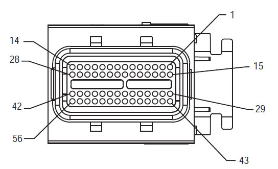
56-Way Parring Connector Vis
[/fusion_text][/fusion_builder_column][fusion_builder_column type=”1_3″ layout=”1_3″ spacing=”” center_content=”no” link=”” target=”_self” min_height=”” hide_on_mobile=”small-visibility,medium-visibility,large-visibility” class=”” id=”” background_color=”” background_image=”” background_image_id=”” background_position=”left top” background_repeat=”no-repeat” hover_type=”none” border_size=”0″ border_color=”” border_style=”solid” border_position=”all” padding_top=”” padding_right=”” padding_bottom=”” padding_left=”” margin_top=”” margin_bottom=”” animation_type=”” animation_direction=”left” animation_speed=”0.3″ animation_offset=”” last=”no”][fusion_imageframe image_id=”14635|full” max_width=”” style_type=”” blur=”” stylecolor=”” hover_type=”none” bordersize=”” bordercolor=”” borderradius=”” align=”center” lightbox=”no” gallery_id=”” lightbox_image=”” lightbox_image_id=”” alt=”High Voltage DC Connector Vis Yazaki Connector” link=”” linktarget=”_self” hide_on_mobile=”small-visibility,medium-visibility,large-visibility” class=”” id=”” animation_type=”” animation_direction=”left” animation_speed=”0.3″ animation_offset=””]https://www.globaltransmissionsupply.com/wp-content/uploads/High-Voltage-DC-Connector-View.jpg[/fusion_imageframe][fusion_text columns=”” column_min_width=”” column_spacing=”” rule_style=”default” rule_size=”” rule_color=”” hide_on_mobile=”small-visibility,medium-visibility,large-visibility” class=”” id=””]
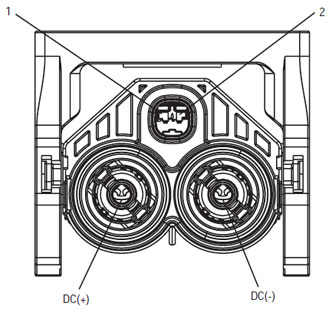
High Voltage DC Connector Vis Yazaki Connector
[/fusion_text][/fusion_builder_column][fusion_builder_column type=”1_3″ layout=”1_3″ spacing=”” center_content=”no” link=”” target=”_self” min_height=”” hide_on_mobile=”small-visibility,medium-visibility,large-visibility” class=”” id=”” background_color=”” background_image=”” background_image_id=”” background_position=”left top” background_repeat=”no-repeat” hover_type=”none” border_size=”0″ border_color=”” border_style=”solid” border_position=”all” padding_top=”” padding_right=”” padding_bottom=”” padding_left=”” margin_top=”” margin_bottom=”” animation_type=”” animation_direction=”left” animation_speed=”0.3″ animation_offset=”” last=”no”][fusion_imageframe image_id=”14213|medium” max_width=”” style_type=”” blur=”” stylecolor=”” hover_type=”none” bordersize=”” bordercolor=”” borderradius=”” align=”center” lightbox=”no” gallery_id=”” lightbox_image=”” lightbox_image_id=”” alt=”Mating Connector View Deutsch 19 – Vei” link=”” linktarget=”_self” hide_on_mobile=”small-visibility,medium-visibility,large-visibility” class=”” id=”” animation_type=”” animation_direction=”left” animation_speed=”0.3″ animation_offset=””]https://www.globaltransmissionsupply.com/wp-content/uploads/Eaton-Fuller-Harness-Connector-View-300×289.jpg[/fusion_imageframe][fusion_text columns=”” column_min_width=”” column_spacing=”” rule_style=”default” rule_size=”” rule_color=”” hide_on_mobile=”small-visibility,medium-visibility,large-visibility” class=”” id=””]
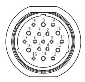
Mating Connector View Deutsch 19 – Vei
[/fusion_text][/fusion_builder_column][/fusion_builder_row][/fusion_builder_container][fusion_builder_container hundred_percent=”no” hundred_percent_height=”no” hundred_percent_height_scroll=”no” hundred_percent_height_center_content=”yes” equal_height_columns=”no” menu_anchor=”” hide_on_mobile=”small-visibility,medium-visibility,large-visibility” status=”published” publish_date=”” class=”” id=”” background_color=”” background_image=”” background_position=”center center” background_repeat=”no-repeat” fade=”no” background_parallax=”none” enable_mobile=”no” parallax_speed=”0.3″ video_mp4=”” video_webm=”” video_ogv=”” video_url=”” video_aspect_ratio=”16:9″ video_loop=”yes” video_mute=”yes” video_preview_image=”” border_size=”” border_color=”” border_style=”solid” margin_top=”” margin_bottom=”” padding_top=”” padding_right=”” padding_bottom=”” padding_left=””][fusion_builder_row][fusion_builder_column type=”1_1″ layout=”1_1″ spacing=”” center_content=”no” link=”” target=”_self” min_height=”” hide_on_mobile=”small-visibility,medium-visibility,large-visibility” class=”” id=”” background_image_id=”” background_color=”#000000″ background_image=”” background_position=”left top” undefined=”” background_repeat=”no-repeat” hover_type=”none” border_size=”0″ border_color=”” border_style=”solid” border_position=”all” padding_top=”” padding_right=”” padding_bottom=”” padding_left=”” margin_top=”” margin_bottom=”” animation_type=”” animation_direction=”left” animation_speed=”0.3″ animation_offset=”” last=”no”][fusion_text columns=”” column_min_width=”” column_spacing=”” rule_style=”default” rule_size=”” rule_color=”” hide_on_mobile=”small-visibility,medium-visibility,large-visibility” class=”” id=””]
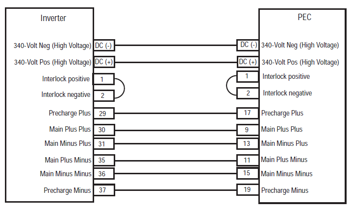
MERK: Referere til Eaton Hybrid Component og Connector Location for Connector Steder i MY08 Systems
[/fusion_text][/fusion_builder_column][fusion_builder_column type=”1_1″ layout=”1_1″ spacing=”” center_content=”no” link=”” target=”_self” min_height=”” hide_on_mobile=”small-visibility,medium-visibility,large-visibility” class=”” id=”” background_color=”” background_image=”” background_image_id=”” background_position=”left top” background_repeat=”no-repeat” hover_type=”none” border_size=”0″ border_color=”” border_style=”solid” border_position=”all” padding_top=”” padding_right=”” padding_bottom=”” padding_left=”” margin_top=”” margin_bottom=”” animation_type=”” animation_direction=”left” animation_speed=”0.3″ animation_offset=”” last=”no”][fusion_imageframe image_id=”14666|full” max_width=”” style_type=”” blur=”” stylecolor=”” hover_type=”none” bordersize=”” bordercolor=”” borderradius=”” align=”center” lightbox=”no” gallery_id=”” lightbox_image=”” lightbox_image_id=”” alt=”Inverter PEC connectors Eaton Fuller Hybrid transmission” link=”” linktarget=”_self” hide_on_mobile=”small-visibility,medium-visibility,large-visibility” class=”” id=”” animation_type=”” animation_direction=”left” animation_speed=”0.3″ animation_offset=””]https://www.globaltransmissionsupply.com/wp-content/uploads/Inverter-PEC-connectors.png[/fusion_imageframe][/fusion_builder_column][/fusion_builder_row][/fusion_builder_container][fusion_builder_container hundred_percent=”no” hundred_percent_height=”no” hundred_percent_height_scroll=”no” hundred_percent_height_center_content=”yes” equal_height_columns=”no” menu_anchor=”” hide_on_mobile=”small-visibility,medium-visibility,large-visibility” status=”published” publish_date=”” class=”” id=”” background_color=”” background_image=”” background_position=”center center” background_repeat=”no-repeat” fade=”no” background_parallax=”none” enable_mobile=”no” parallax_speed=”0.3″ video_mp4=”” video_webm=”” video_ogv=”” video_url=”” video_aspect_ratio=”16:9″ video_loop=”yes” video_mute=”yes” video_preview_image=”” border_size=”” border_color=”” border_style=”solid” margin_top=”” margin_bottom=”” padding_top=”” padding_right=”” padding_bottom=”” padding_left=””][fusion_builder_row][fusion_builder_column type=”1_1″ layout=”1_1″ spacing=”” center_content=”no” link=”” target=”_self” min_height=”” hide_on_mobile=”small-visibility,medium-visibility,large-visibility” class=”” id=”” background_color=”” background_image=”” background_image_id=”” background_position=”left top” background_repeat=”no-repeat” hover_type=”none” border_size=”0″ border_color=”” border_style=”solid” border_position=”all” padding_top=”” padding_right=”” padding_bottom=”” padding_left=”” margin_top=”” margin_bottom=”” animation_type=”” animation_direction=”left” animation_speed=”0.3″ animation_offset=”” last=”no”][fusion_modal name=”warnings_cautions” title=”advarsler & Forsiktighetsregler” size=”large” background=”” border_color=”” show_footer=”yes” class=”” id=””]Fare: Fare indikerer at du vil bli alvorlig skadet eller drept hvis ikke følger den angitte prosedyren.
Advarsel: Advarsel indikerer en umiddelbar fare, noe som kan føre til alvorlig personskade hvis du ikke følger den angitte prosedyren.
Forsiktighet: Forsiktig indikerer kjøretøy eller materielle skader kan oppstå hvis du ikke følger den angitte prosedyren.
Merk: Merk indikerer ytterligere detalj som vil understøtte diagnostisering eller reparasjon av en komponent / system.
Følg de angitte prosedyrene i angitt for å unngå personskader:
1. Ved høy spenning membranene er omkring kjøretøyet og sperren er montert på den anvendte PEF, den eneste personen som skal få lov til å starte bilen er den personen som signerte lockout tag.
2. Før du arbeider på et kjøretøy eller forlate førerhuset mens motoren er i gang, du bør plassere girspaken i “N” sett på parkeringsbremsen, og blokkere hjulene.
3. Av sikkerhetsmessige grunner, alltid i inngrep med bremser før velge girstillingene fra “N.”
4. Før du starter et kjøretøy alltid sitte i førersetet, velg “N” på girspaken, og sett på parkeringsbrems.
5. I biler med ePTO, motoren og / eller
Motor / Generator kan starte i ePTO modus. Utfør aldri vedlikehold eller arbeid på kjøretøy, mens i denne modusen.
6. 12-Volt Battery positiv (+) og negative (-) må koples fra før enhver sveising på en hvilken som helst hybrid utstyrt kjøretøy.
Forsiktighet: Følg de angitte prosedyrene i angitt for å unngå feil på utstyr eller skade.
Forsiktighet: Ikke slipp parkeringsbremsen eller forsøke å velge et gir til lufttrykket er på riktig nivå.
Forsiktighet: For å unngå skade på transmisjonen under slep sted girspaken i “N” og løfte drivhjulene av bakken eller frakoble drivlinjen.
Høyspent advarsler & Forsiktighetsregler
- Bruk CO2 eller kjemisk brannslukkere.
- Den høyspente ledninger er dekket i oransje isolasjon eller korrugert slange og merket med advarsler på kontaktene.
- Alle Eaton® Hybrid Diesel / elektriske biler vil bli merket med ‘Hybrid’ på utsiden av kjøretøyet, sammen med skift etiketten på dashbordet.
- Referer til OEM for en bestemt plassering av chassismontert hybrid komponenter.
- IKKE kutt i de oransje høyspenningskabler.
- IKKE kutt i eller åpne PEC.
- IKKE kutt i eller åpne DC / DC Converter.
- IKKE kutt i eller åpne Inverter.
En buffersone må settes opp og høy spenning isoleres gummihansker (klasse 0 med skinn beskyttere) Det kreves før arbeider på høy spenning. Hvis du ikke følger disse instruksjonene kan føre til alvorlig personskade eller død.
Gummiisolerte hansker som må brukes ved arbeid med høy spenning system er klasse 0 med skinn beskyttere. Gummihansker bør testes før hver bruk etter gummi isolasjonshansker testprosedyren finnes i “Diagnostic Tools / tjeneste Publikasjoner” på side 6. Hvis du ikke følger disse instruksjonene kan føre til alvorlig personskade eller død.
Før inspeksjon eller arbeider på noen høyspentkabler eller komponenter “High-Voltage service Shutdown og Power-Up Prosedyre” på side 4 bør følges. Hvis du ikke følger disse instruksjonene kan føre til alvorlig personskade eller død.
Låsingen og Tagout enheter skal bare fjernes av teknikeren som plasseres på låse og Tagout anordninger på kjøretøyet. Hvis du ikke følger disse instruksjonene kan føre til alvorlig personskade eller død.
Høyspente gummiisolerte hansker (klasse 0 med skinn beskyttere) må brukes når du arbeider på noen
høyspenningskabler. “High-Voltage service Shutdown og Power-Up Prosedyre” på side 4 må følges før fjerning av eventuelle høyspenningskabler. Hvis du ikke følger disse instruksjonene kan føre til alvorlig personskade eller død.
Høyspentkabler og ledninger er oransje og inneholder en advarsel etikett på kontaktene. Høyspente komponenter er markert med en etikett. Høyspente gummiisolerte hansker (klasse 0 med skinn beskyttere) må brukes når du arbeider på noen av disse komponentene. Hvis du ikke følger disse instruksjonene kan føre til alvorlig personskade eller død.
Høyspent service avslåingsprosedyrer

1. Følg “High-Voltage Work Area” prosedyre.
2. Finn den røde PEC servicebryter på forsiden av PEC og presse slå av.
3. Fjern Tjenesten Switch Cover og installere Lockout Bracket (J48506).
4. Fest tag til Lockout Bracket.
5. Sørg for at PEC servicebryter kan ikke flytte fra seg stillingen.
6. La systemet for å sette i minst 5 minutter for å løsne høyspennings.
7. Koble ServiceRanger og vise data Monitor PID 116 kalt “High-Voltage Batteri Potential”. Bruk SPN 520323 for J1939-tilkobling “Battery Voltage RB” (Relay Box).
8. Spenningen skal være 30 volt eller mindre. Hvis spenningen er over 30 volt, fungerer ikke på kjøretøyet og ta kontakt Eaton® på 1-800-826-HELP (4357).
9. Vri tenningsnøkkelen av og fortsette å reparere eller trinn i feilsøkingen.
Merk: Spenningen faller til null når nøkkelen er off.
Høyspent service Strøm-Up Prosedyre
1. Installer alle høyspente kontakter inn i deres låste posisjoner.
2. Hvis du er den personen som arbeider på kjøretøyet, fjerne låsingen brakett og tag.
3. Sett på Lockout Bracket over servicebryter.
4. Trekk Tjenesten Bytt ut og la bilen satt for 2 minutter.
5. Start vehicle when appropriate.[/fusion_modal][fusion_modal name=”component_location” title=”Eaton Hybrid Component og Connector Location ” size=”large” background=”#ffffff” border_color=”” show_footer=”yes” class=”” id=””]

[/fusion_modal][fusion_modal name=”component_location2″ title=”Eaton Hybrid Component og Connector Location MY09 Systems” size=”large” background=”#ffffff” border_color=”” show_footer=”yes” class=”” id=””]

[/fusion_modal][/fusion_builder_column][/fusion_builder_row][/fusion_builder_container][fusion_builder_container hundred_percent=”no” hundred_percent_height=”no” hundred_percent_height_scroll=”no” hundred_percent_height_center_content=”yes” equal_height_columns=”no” menu_anchor=”” hide_on_mobile=”small-visibility,medium-visibility,large-visibility” status=”published” publish_date=”” class=”” id=”” background_color=”” background_image=”” background_position=”center center” background_repeat=”no-repeat” fade=”no” background_parallax=”none” enable_mobile=”no” parallax_speed=”0.3″ video_mp4=”” video_webm=”” video_ogv=”” video_url=”” video_aspect_ratio=”16:9″ video_loop=”yes” video_mute=”yes” video_preview_image=”” border_size=”” border_color=”” border_style=”solid” margin_top=”” margin_bottom=”” padding_top=”” padding_right=”” padding_bottom=”” padding_left=””][fusion_builder_row][fusion_builder_column type=”1_1″ layout=”1_1″ spacing=”” center_content=”no” link=”” target=”_self” min_height=”” hide_on_mobile=”small-visibility,medium-visibility,large-visibility” class=”” id=”” background_color=”” background_image=”” background_image_id=”” background_position=”left top” background_repeat=”no-repeat” hover_type=”none” border_size=”0″ border_color=”” border_style=”solid” border_position=”all” padding_top=”” padding_right=”” padding_bottom=”” padding_left=”” margin_top=”” margin_bottom=”” animation_type=”” animation_direction=”left” animation_speed=”0.3″ animation_offset=”” last=”no”][fusion_content_boxes layout=”clean-horizontal” columns=”2″ title_size=”18px” heading_size=”3″ title_color=”#ffffff” body_color=”#ffffff” backgroundcolor=”#4f4f4f” icon=”” iconflip=”” iconrotate=”” iconspin=”no” iconcolor=”” icon_circle=”” icon_circle_radius=”” circlecolor=”” circlebordersize=”” circlebordercolor=”” outercirclebordersize=”” outercirclebordercolor=”” icon_size=”” icon_hover_type=”” hover_accent_color=”” image=”” image_id=”” image_width=”” image_height=”” link_type=”” button_span=”” link_area=”” link_target=”” icon_align=”left” animation_type=”” animation_delay=”” animation_offset=”” animation_direction=”left” animation_speed=”0.3″ margin_top=”” margin_bottom=”” hide_on_mobile=”small-visibility,medium-visibility,large-visibility” class=”” id=””][fusion_content_box title=”SKRITT 1. Bekreft FMIs stede.” backgroundcolor=”” icon=”” iconflip=”” iconrotate=”” iconspin=”no” iconcolor=”” circlecolor=”” circlebordersize=”” circlebordercolor=”” outercirclebordersize=”” outercirclebordercolor=”” image=”” image_id=”” image_width=”” image_height=”” link=”” linktext=”Les mer” link_target=”” animation_type=”” animation_direction=”left” animation_speed=”0.3″ animation_offset=””]
- Gjennomgå og følg advarsler & Forsiktighetsregler.
- Hent Aktive feilkoder og FMIs med ServiceRanger bruker 9-Way Diagnostic Connector.
Fare: Se Stoppe av høyspenningstjeneste og oppstartprosedyrer. Følg fremgangsmåten for å unngå sjokk, brenne eller død feil håndtert høyspent. - Hvilke FMIs er til stede
- Hvis feilkode 116 IMF 14 er notert, gå til trinn 9.
- Hvis feilkode 116 IMF 10 er notert, gå til trinn 2.
- If no Fault Codes are listed, The Service Switch was pushed in. Gå til trinn 10.
[/fusion_content_box][fusion_content_box title=”SKRITT 2. Verify Data Monitor parameters.” backgroundcolor=”” icon=”” iconflip=”” iconrotate=”” iconspin=”no” iconcolor=”” circlecolor=”” circlebordersize=”” circlebordercolor=”” outercirclebordersize=”” outercirclebordercolor=”” image=”” image_id=”” image_width=”” image_height=”” link=”” linktext=”Les mer” link_target=”” animation_type=”” animation_direction=”left” animation_speed=”0.3″ animation_offset=””]
- tast på.
- Koble ServiceRanger til 9-Way Diagnostic Connector i førerhuset.
- Velg “Data Monitor” alternativet.
- View the Battery Pack Voltage (BCU1) PID 118 in the high- voltage Battery list:
- If the Battery Pack Voltage (BCU1) PID 118 is greater than 200 volt, gå til trinn 3.
- If the Battery Pack Voltage (BCU1) PID 118 er mindre enn 200 volt, erstatte kraftelektronikk Carrier (PEC), gå deretter til trinn 10.
[/fusion_content_box][/fusion_content_boxes][fusion_content_boxes layout=”clean-horizontal” columns=”2″ title_size=”18px” heading_size=”3″ title_color=”#ffffff” body_color=”#ffffff” backgroundcolor=”#4f4f4f” icon=”” iconflip=”” iconrotate=”” iconspin=”no” iconcolor=”” icon_circle=”” icon_circle_radius=”” circlecolor=”” circlebordersize=”” circlebordercolor=”” outercirclebordersize=”” outercirclebordercolor=”” icon_size=”” icon_hover_type=”” hover_accent_color=”” image=”” image_id=”” image_width=”” image_height=”” link_type=”” button_span=”” link_area=”” link_target=”” icon_align=”left” animation_type=”” animation_delay=”” animation_offset=”” animation_direction=”left” animation_speed=”0.3″ margin_top=”” margin_bottom=”” hide_on_mobile=”small-visibility,medium-visibility,large-visibility” class=”” id=””][fusion_content_box title=”SKRITT 3. Verify continuity of Inverter connector circuits.” backgroundcolor=”” icon=”” iconflip=”” iconrotate=”” iconspin=”no” iconcolor=”” circlecolor=”” circlebordersize=”” circlebordercolor=”” outercirclebordersize=”” outercirclebordercolor=”” image=”” image_id=”” image_width=”” image_height=”” link=”” linktext=”Les mer” link_target=”” animation_type=”” animation_direction=”left” animation_speed=”0.3″ animation_offset=””]
- Key off.
- If the vehicle is not equipped with a DC/DC Converter or APG, skip this step.
- Using ASTM Class 0 electrical insulating rubber gloves with leather protectors, disconnect the DC cable for the DC/DC Converter and APG at the PEC.
- With the key off, temporarily remove the Lockout Bracket and pull the Service Switch out.
- tast på.
- Er Feilkode 116 IMF 10 still Active in ServiceRanger?
- Hvis feilkode 116 IMF 10 is Active with the DC/DC Converter and APG disconnected, gå til trinn 4.
- Hvis feilkode 116 IMF 10 is no longer Active with the DC/DC Converter and APG disconnected, key off and reinstall the Lockout Bracket on the PEC. Replace the Power Electronics Carrier (PEC), gå deretter til trinn 10.
[/fusion_content_box][fusion_content_box title=”SKRITT 4. Verify continuity of PEC connector circuits to ground.” backgroundcolor=”” icon=”” iconflip=”” iconrotate=”” iconspin=”” iconcolor=”” circlecolor=”” circlebordersize=”” circlebordercolor=”” outercirclebordersize=”” outercirclebordercolor=”” image=”” image_id=”” image_width=”” image_height=”” link=”” linktext=”” link_target=”” animation_type=”” animation_direction=”left” animation_speed=”0.3″ animation_offset=””]
- Key off.
- Koble fra PEC 19-Way Connector.
- Temporarily remove the Lockout Bracket and pull the Service Switch out.
Merk: Ensure the Key Switch is off. - Measure resistance at the PEC 19-Way Connector Terminal at the following pins:
- pin 17 til Pin 19
- pin 9 til Pin 11
- pin 13 til Pin 15
- If the resistance between Pins 17 og Pin 19 er 112-122 ohm og motstanden fra Pin 9 til Pin 11 og Pin 13 til Pin 15 er hver 33-37 ohm, gå til trinn 5.
- Hvis motstanden er ute av rekkevidde, gå til trinn 6.
[/fusion_content_box][/fusion_content_boxes][fusion_content_boxes layout=”clean-horizontal” columns=”2″ title_size=”18px” heading_size=”3″ title_color=”#ffffff” body_color=”#ffffff” backgroundcolor=”#4f4f4f” icon=”” iconflip=”” iconrotate=”” iconspin=”no” iconcolor=”” icon_circle=”” icon_circle_radius=”” circlecolor=”” circlebordersize=”” circlebordercolor=”” outercirclebordersize=”” outercirclebordercolor=”” icon_size=”” icon_hover_type=”” hover_accent_color=”” image=”” image_id=”” image_width=”” image_height=”” link_type=”” button_span=”” link_area=”” link_target=”” icon_align=”left” animation_type=”” animation_delay=”” animation_offset=”” animation_direction=”left” animation_speed=”0.3″ margin_top=”” margin_bottom=”” hide_on_mobile=”small-visibility,medium-visibility,large-visibility” class=”” id=””][fusion_content_box title=”SKRITT 5. Verify continuity of Inverter connector circuits to ground.” backgroundcolor=”” icon=”” iconflip=”” iconrotate=”” iconspin=”no” iconcolor=”” circlecolor=”” circlebordersize=”” circlebordercolor=”” outercirclebordersize=”” outercirclebordercolor=”” image=”” image_id=”” image_width=”” image_height=”” link=”” linktext=”Les mer” link_target=”” animation_type=”” animation_direction=”left” animation_speed=”0.3″ animation_offset=””]
- Key off.
- Reconnect the PEC 19-Way Connector.
- Koble omformeren 56-Way Connector.
- Inspect the connector pins for damaged, corroded and/or loose wires.
- Measure resistance between the Inverter 56-Way Connector at the following pins:
- pin 29 til Pin 37
- pin 30 til Pin 35
- pin 31 til Pin 36 Merk: Forsiktig bøye Inverter 56-veis kontakt sele nær kontakten mens overvåking motstandsverdiene.
- Hvis motstanden mellom Pin 29 og Pin 37 er 112-122 ohm og motstanden fra Pin 30 til Pin 35 og Pin 31 til Pin 36 er hver 33-37 ohm, push the Service Switch on the PEC and reinstall the Lockout Bracket. Gå til trinn 8.
- Hvis motstanden er ute av rekkevidde, repair the Hybrid Harness between the PEC and Inverter, gå deretter til trinn 10.
[/fusion_content_box][fusion_content_box title=”SKRITT 6. Verify continuity of PEC connector circuits.” backgroundcolor=”” icon=”” iconflip=”” iconrotate=”” iconspin=”” iconcolor=”” circlecolor=”” circlebordersize=”” circlebordercolor=”” outercirclebordersize=”” outercirclebordercolor=”” image=”” image_id=”” image_width=”” image_height=”” link=”” linktext=”” link_target=”” animation_type=”” animation_direction=”left” animation_speed=”0.3″ animation_offset=””]
- Key off.
- Remove the Air Filter Cover and Air Filter from the PEC. Refer to TRSM1000 for procedures.*
- An Inertia Switch is located at the front of the PEC inside the box and viewable when the Air Filter is removed.
- Using ASTM Class 0 electrical insulating rubber gloves with leather protectors, press the button on the top of the Inertia Switch until heard or felt a click. This switch must be depressed a set distance to reset the switch.
- Measure resistance at the PEC 19-Way Connector Terminal at the following pins:
- pin 17 til Pin 19
- pin 9 til Pin 11
- pin 13 til Pin 15
- qIf the resistance between Pin 17 og Pin 19 er 112-122 ohm og motstanden fra Pin 9 til Pin 11 og Pin 13 til Pin 15 er hver 33-37 ohm, the Inertia Switch was tripped. Test is complete. Gå til trinn 10.
- Hvis motstanden er ute av rekkevidde, push in the Service Switch on the PEC and reinstall the Lockout Bracket, gå deretter til trinn 7.
[/fusion_content_box][/fusion_content_boxes][fusion_content_boxes layout=”clean-horizontal” columns=”2″ title_size=”18px” heading_size=”3″ title_color=”#ffffff” body_color=”#ffffff” backgroundcolor=”#4f4f4f” icon=”” iconflip=”” iconrotate=”” iconspin=”no” iconcolor=”” icon_circle=”” icon_circle_radius=”” circlecolor=”” circlebordersize=”” circlebordercolor=”” outercirclebordersize=”” outercirclebordercolor=”” icon_size=”” icon_hover_type=”” hover_accent_color=”” image=”” image_id=”” image_width=”” image_height=”” link_type=”” button_span=”” link_area=”” link_target=”” icon_align=”left” animation_type=”” animation_delay=”” animation_offset=”” animation_direction=”left” animation_speed=”0.3″ margin_top=”” margin_bottom=”” hide_on_mobile=”small-visibility,medium-visibility,large-visibility” class=”” id=””][fusion_content_box title=”SKRITT 7. Verify continuity of Inverter connector circuits.” backgroundcolor=”” icon=”” iconflip=”” iconrotate=”” iconspin=”no” iconcolor=”” circlecolor=”” circlebordersize=”” circlebordercolor=”” outercirclebordersize=”” outercirclebordercolor=”” image=”” image_id=”” image_width=”” image_height=”” link=”” linktext=”Les mer” link_target=”” animation_type=”” animation_direction=”left” animation_speed=”0.3″ animation_offset=””]
- Key off.
- Disconnect the DC High-Voltage Cable at the PEC Bulkhead and at the Inverter Bulkhead.
- Measure resistance between the Low-Voltage Interlock Pins on the PEC side of the DC High-Voltage Cable:
Merk: The Interlock Pins are the two small spade terminals located in the same opening.- If the resistance is 0–0.3 ohms between the Interlock Loop Pins, erstatte kraftelektronikk Carrier (PEC), gå deretter til trinn 10.
- Hvis motstanden er ute av rekkevidde, erstatte den like høyspenningskabel, gå deretter til trinn 10.
[/fusion_content_box][fusion_content_box title=”SKRITT 8. Verify continuity of DC Cable from PEC to Inverter Connector circuits.” backgroundcolor=”” icon=”” iconflip=”” iconrotate=”” iconspin=”” iconcolor=”” circlecolor=”” circlebordersize=”” circlebordercolor=”” outercirclebordersize=”” outercirclebordercolor=”” image=”” image_id=”” image_width=”” image_height=”” link=”” linktext=”” link_target=”” animation_type=”” animation_direction=”left” animation_speed=”0.3″ animation_offset=””]
- Key off.
- Disconnect the DC High-Voltage Cable at the PEC Bulkhead and the Inverter Bulkhead.
- Measure the resistance of each high-voltage circuit on the cable:
- If the resistance of each high-voltage circuit in the cable is 1 ohm eller mindre, erstatte Inverter, gå deretter til trinn 10.
- Hvis motstanden er ute av rekkevidde, replace the DC High-Voltage Cable, gå deretter til trinn 10.
[/fusion_content_box][/fusion_content_boxes][fusion_content_boxes layout=”clean-horizontal” columns=”2″ title_size=”18px” heading_size=”3″ title_color=”#ffffff” body_color=”#ffffff” backgroundcolor=”#4f4f4f” icon=”” iconflip=”” iconrotate=”” iconspin=”no” iconcolor=”” icon_circle=”” icon_circle_radius=”” circlecolor=”” circlebordersize=”” circlebordercolor=”” outercirclebordersize=”” outercirclebordercolor=”” icon_size=”” icon_hover_type=”” hover_accent_color=”#f41000″ image=”” image_id=”” image_width=”” image_height=”” link_type=”” button_span=”” link_area=”” link_target=”” icon_align=”left” animation_type=”” animation_delay=”” animation_offset=”” animation_direction=”left” animation_speed=”0.3″ margin_top=”” margin_bottom=”” hide_on_mobile=”small-visibility,medium-visibility,large-visibility” class=”” id=””][fusion_content_box title=”SKRITT 9. Verify Data Monitor parameters.” backgroundcolor=”” icon=”” iconflip=”” iconrotate=”” iconspin=”” iconcolor=”” circlecolor=”” circlebordersize=”” circlebordercolor=”” outercirclebordersize=”” outercirclebordercolor=”” image=”” image_id=”” image_width=”” image_height=”” link=”” linktext=”” link_target=”” animation_type=”” animation_direction=”left” animation_speed=”0.3″ animation_offset=””]
- Koble ServiceRanger til 9-Way Diagnostic Connector i førerhuset.
- Velg “Data Monitor” alternativet.
- View the following parameters in the High-Voltage Battery list.
- Battery Pack Voltage (BCU1) PID 118
- Battery Voltage PID 116
- If the voltage readings on PID 116 og PID 118 are within 10 volt fra hverandre, erstatte kraftelektronikk Carrier (PEC), gå deretter til trinn 10.
- If the voltage readings on PID 116 og PID 118 are greater than 10 volt fra hverandre, erstatte Inverter, gå deretter til trinn 10.
[/fusion_content_box][fusion_content_box title=”SKRITT 10. Bekreft reparasjon.” backgroundcolor=”” icon=”” iconflip=”” iconrotate=”” iconspin=”no” iconcolor=”” circlecolor=”” circlebordersize=”” circlebordercolor=”” outercirclebordersize=”” outercirclebordercolor=”” image=”” image_id=”” image_width=”” image_height=”” link=”” linktext=”Les mer” link_target=”” animation_type=”” animation_direction=”left” animation_speed=”0.3″ animation_offset=””]
- Key off.
- Koble til alle kontaktene og den negative batterikabelen.
- tast på.
- klare koder, se Klare Inaktive feil.
- Kjøre bilen og forsøke å nullstille koden.
- Se etter koder, se Vis aktive og inaktive Feil.
- Hvis ingen koder, testen er fullført.
- Hvis feilkode 116 vises, Kontakt Eaton kl 1- 800-826-HJELP (4357). Repeat this Step (Skritt 10).
- Hvis en kode annet enn 116 vises, se Feilkode indeksliste.
[/fusion_content_box][/fusion_content_boxes][/fusion_builder_column][/fusion_builder_row][/fusion_builder_container][fusion_global id=”13788″]