[fusion_builder_container hundred_percent=”no” hundred_percent_height=”no” hundred_percent_height_scroll=”no” hundred_percent_height_center_content=”yes” equal_height_columns=”no” menu_anchor=”” hide_on_mobile=”small-visibility,medium-visibility,large-visibility” status=”published” publish_date=”” class=”” id=”” background_color=”” background_image=”” background_position=”center center” background_repeat=”no-repeat” fade=”no” background_parallax=”none” enable_mobile=”no” parallax_speed=”0.3″ video_mp4=”” video_webm=”” video_ogv=”” video_url=”” video_aspect_ratio=”16:9″ video_loop=”yes” video_mute=”yes” video_preview_image=”” border_size=”” border_color=”” border_style=”solid” margin_top=”35″ margin_bottom=”” padding_top=”” padding_right=”” padding_bottom=”” padding_left=””][fusion_builder_row][fusion_builder_column type=”1_1″ layout=”1_1″ spacing=”” center_content=”no” link=”” target=”_self” min_height=”” hide_on_mobile=”small-visibility,medium-visibility,large-visibility” class=”” id=”” background_color=”” background_image=”” background_image_id=”” background_position=”left top” background_repeat=”no-repeat” hover_type=”none” border_size=”0″ border_color=”” border_style=”solid” border_position=”all” padding_top=”” padding_right=”” padding_bottom=”” padding_left=”” margin_top=”” margin_bottom=”” animation_type=”” animation_direction=”left” animation_speed=”0.3″ animation_offset=”” last=”no”][fusion_text columns=”” column_min_width=”” column_spacing=”” rule_style=”default” rule_size=”” rule_color=”” hide_on_mobile=”small-visibility,medium-visibility,large-visibility” class=”” id=””]
Eaton Fuller hybride transmissie Fault Code 116 – High Voltage Relays -(MY08 Systems)
[/fusion_text][/fusion_builder_column][/fusion_builder_row][/fusion_builder_container][fusion_builder_container hundred_percent=”no” hundred_percent_height=”no” hundred_percent_height_scroll=”no” hundred_percent_height_center_content=”yes” equal_height_columns=”no” menu_anchor=”” hide_on_mobile=”small-visibility,medium-visibility,large-visibility” status=”published” publish_date=”” class=”” id=”” background_color=”” background_image=”” background_position=”center center” background_repeat=”no-repeat” fade=”no” background_parallax=”none” enable_mobile=”no” parallax_speed=”0.3″ video_mp4=”” video_webm=”” video_ogv=”” video_url=”” video_aspect_ratio=”16:9″ video_loop=”yes” video_mute=”yes” video_preview_image=”” border_size=”” border_color=”” border_style=”solid” margin_top=”” margin_bottom=”” padding_top=”” padding_right=”” padding_bottom=”” padding_left=””][fusion_builder_row][fusion_builder_column type=”1_1″ layout=”1_1″ spacing=”” center_content=”no” link=”” target=”_self” min_height=”” hide_on_mobile=”small-visibility,medium-visibility,large-visibility” class=”” id=”” background_color=”” background_image=”” background_image_id=”” background_position=”left top” background_repeat=”no-repeat” hover_type=”none” border_size=”0″ border_color=”” border_style=”solid” border_position=”all” padding_top=”” padding_right=”” padding_bottom=”” padding_left=”” margin_top=”” margin_bottom=”” animation_type=”” animation_direction=”left” animation_speed=”0.3″ animation_offset=”” last=”no”][fusion_text columns=”” column_min_width=”” column_spacing=”” rule_style=”default” rule_size=”” rule_color=”” hide_on_mobile=”small-visibility,medium-visibility,large-visibility” class=”” id=””]
Storing code voor Eaton Hybrid Drive Systems modellen (MY08) EH-8E306A-U, EH-8E306A-UPG, EH-8E306A-UP, EH-8E306A-CD, EH-8E306A-T, EH-6E606B-CD. Lees hieronder om te leren hoe om te testen, wissen en bevestig foutcode fouten voor uw Freightliner, Mack, Peterbilt, Kenworth, Volvo, Internationale, en heavy-duty truck en apparatuur. The High-Voltage Relays are located inside the Power Electronics Carrier (PEC) in de relaiskast unit. There is 1 precharge relay on the positive side, an additional relay on the positive, en 1 on the negative for a total of 3. Deze relais zijn normaal open wanneer het systeem is uitgeschakeld. De relais worden bestuurd door de inverter.
Fout code 116 – High Voltage Relays Detection
De volgende randvoorwaarden moet worden voldaan voordat het systeem de fout detecteert:
- Inverter ontsteekspanning groter is dan 7 volt en minder dan 16 volt.
Notitie: Bij het oplossen van een inactieve code wordt verwezen naar de Product Diagnostic Mode (PDM)
Voorwaarden voor Set Fault Code Active
- IMF 10 is set when the Inverter detects the input voltage measured at the capacitor is less than 210 volts within 3 seconds after the sub-relay closed in the Relay Box.
- IMF 14 is set when only the negative relay in the Relay Box is on and capacitor voltage decreases less than 10 volts/5 seconds when initial capacitor voltage was greater than 200 volts and motor speed less than 500 min-1, or there is a detect error in the initial check.
Terugval Als Fault Code 116 ingesteld gebeurt het volgende:
- Amber “Controle Hybrid” licht knippert FMI 10 and remains solid for FMI 14.
- Storing wordt opgeslagen in HCM geheugen.
- Inverter sluit hoogspanningsnet off.
- HCM blijft het hybride voertuig besturen in een diesel-only mode.
- Transmission defaults beginnen versnelling naar de 1e.
[/fusion_text][fusion_text columns=”” column_min_width=”” column_spacing=”” rule_style=”default” rule_size=”” rule_color=”” hide_on_mobile=”small-visibility,medium-visibility,large-visibility” class=”” id=””]
Voorwaarden voor Set Fault Code Inactieve
Alleen Inactieve fouten kunnen worden gewist uit de Unit Transmission Electronic Control (TECU) of HCM geschiedenis met behulp ServiceRanger. De TECU verdwijnt automatisch de fouten uit de geschiedenis na 200 uur en de HCM verdwijnt automatisch de fouten uit de geschiedenis na de storing actief is geweest voor 200 uur.
Deze fout code kan worden veroorzaakt door een van de volgende:
- IMF 10
- PEC
- APG
- inverter
- DC high-voltage cable
- DC cable interlock loops
- Inertia Switch
- dienst Switch
- IMF 14
- inverter
- PEC
[/fusion_text][/fusion_builder_column][/fusion_builder_row][/fusion_builder_container][fusion_builder_container hundred_percent=”no” hundred_percent_height=”no” hundred_percent_height_scroll=”no” hundred_percent_height_center_content=”yes” equal_height_columns=”no” menu_anchor=”” hide_on_mobile=”small-visibility,medium-visibility,large-visibility” status=”published” publish_date=”” class=”” id=”” background_color=”” background_image=”” background_position=”center center” background_repeat=”no-repeat” fade=”no” background_parallax=”none” enable_mobile=”no” parallax_speed=”0.3″ video_mp4=”” video_webm=”” video_ogv=”” video_url=”” video_aspect_ratio=”16:9″ video_loop=”yes” video_mute=”yes” video_preview_image=”” border_size=”” border_color=”” border_style=”solid” margin_top=”” margin_bottom=”” padding_top=”” padding_right=”” padding_bottom=”” padding_left=””][fusion_builder_row][fusion_builder_column type=”1_1″ layout=”1_1″ spacing=”” center_content=”no” link=”” target=”_self” min_height=”” hide_on_mobile=”small-visibility,medium-visibility,large-visibility” class=”” id=”” background_color=”” background_image=”” background_image_id=”” background_position=”left top” background_repeat=”no-repeat” hover_type=”none” border_size=”0″ border_color=”” border_style=”solid” border_position=”all” padding_top=”” padding_right=”” padding_bottom=”” padding_left=”” margin_top=”” margin_bottom=”” animation_type=”” animation_direction=”left” animation_speed=”0.3″ animation_offset=”” last=”no”][fusion_text columns=”” column_min_width=”” column_spacing=”” rule_style=”default” rule_size=”” rule_color=”” hide_on_mobile=”small-visibility,medium-visibility,large-visibility” class=”” id=””]
Fout code 116 – High Voltage Relays Test
[/fusion_text][/fusion_builder_column][/fusion_builder_row][/fusion_builder_container][fusion_builder_container hundred_percent=”no” hundred_percent_height=”no” hundred_percent_height_scroll=”no” hundred_percent_height_center_content=”yes” equal_height_columns=”no” menu_anchor=”” hide_on_mobile=”small-visibility,medium-visibility,large-visibility” status=”published” publish_date=”” class=”” id=”” background_color=”” background_image=”” background_position=”center center” background_repeat=”no-repeat” fade=”no” background_parallax=”none” enable_mobile=”no” parallax_speed=”0.3″ video_mp4=”” video_webm=”” video_ogv=”” video_url=”” video_aspect_ratio=”16:9″ video_loop=”yes” video_mute=”yes” video_preview_image=”” border_size=”” border_color=”” border_style=”solid” margin_top=”” margin_bottom=”” padding_top=”” padding_right=”” padding_bottom=”” padding_left=””][fusion_builder_row][fusion_builder_column type=”1_1″ layout=”1_1″ spacing=”” center_content=”no” link=”” target=”_self” min_height=”” hide_on_mobile=”small-visibility,medium-visibility,large-visibility” class=”” id=”” background_color=”” background_image=”” background_image_id=”” background_position=”left top” background_repeat=”no-repeat” hover_type=”none” border_size=”0″ border_color=”” border_style=”solid” border_position=”all” padding_top=”” padding_right=”” padding_bottom=”” padding_left=”” margin_top=”” margin_bottom=”” animation_type=”” animation_direction=”left” animation_speed=”0.3″ animation_offset=”” last=”no”][fusion_text columns=”” column_min_width=”” column_spacing=”” rule_style=”default” rule_size=”” rule_color=”” hide_on_mobile=”small-visibility,medium-visibility,large-visibility” class=”” id=””]
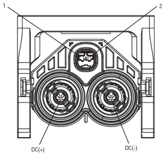
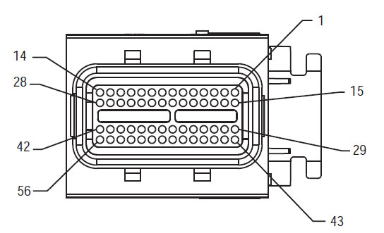
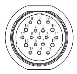
Identificatie van de onderdelen MY08 Systems:
[/fusion_text][/fusion_builder_column][/fusion_builder_row][/fusion_builder_container][fusion_builder_container hundred_percent=”yes” hundred_percent_height=”no” hundred_percent_height_scroll=”no” hundred_percent_height_center_content=”yes” equal_height_columns=”no” menu_anchor=”” hide_on_mobile=”small-visibility,medium-visibility,large-visibility” status=”published” publish_date=”” class=”” id=”” background_color=”” background_image=”” background_position=”center center” background_repeat=”no-repeat” fade=”no” background_parallax=”none” enable_mobile=”no” parallax_speed=”0.3″ video_mp4=”” video_webm=”” video_ogv=”” video_url=”” video_aspect_ratio=”16:9″ video_loop=”yes” video_mute=”yes” video_preview_image=”” border_size=”” border_color=”” border_style=”solid” margin_top=”” margin_bottom=”” padding_top=”” padding_right=”10%” padding_bottom=”” padding_left=”10%”][fusion_builder_row][fusion_builder_column type=”1_3″ layout=”1_3″ spacing=”” center_content=”no” link=”” target=”_self” min_height=”” hide_on_mobile=”small-visibility,medium-visibility,large-visibility” class=”” id=”” background_color=”” background_image=”” background_image_id=”” background_position=”left top” background_repeat=”no-repeat” hover_type=”none” border_size=”0″ border_color=”” border_style=”solid” border_position=”all” padding_top=”” padding_right=”” padding_bottom=”” padding_left=”” margin_top=”” margin_bottom=”” animation_type=”” animation_direction=”left” animation_speed=”0.3″ animation_offset=”” last=”no”][fusion_imageframe image_id=”14474|full” max_width=”” style_type=”” blur=”” stylecolor=”” hover_type=”none” bordersize=”” bordercolor=”” borderradius=”” align=”center” lightbox=”no” gallery_id=”” lightbox_image=”” lightbox_image_id=”” alt=”Delphi 56-Way Mating Connector View” link=”” linktarget=”_self” hide_on_mobile=”small-visibility,medium-visibility,large-visibility” class=”” id=”” animation_type=”” animation_direction=”left” animation_speed=”0.3″ animation_offset=””]https://www.globaltransmissionsupply.com/wp-content/uploads/Inverter-56-Way-Mating-Connector-View.jpg[/fusion_imageframe][fusion_text columns=”” column_min_width=”” column_spacing=”” rule_style=”default” rule_size=”” rule_color=”” hide_on_mobile=”small-visibility,medium-visibility,large-visibility” class=”” id=””]
56-Way Mating Connector View
[/fusion_text][/fusion_builder_column][fusion_builder_column type=”1_3″ layout=”1_3″ spacing=”” center_content=”no” link=”” target=”_self” min_height=”” hide_on_mobile=”small-visibility,medium-visibility,large-visibility” class=”” id=”” background_color=”” background_image=”” background_image_id=”” background_position=”left top” background_repeat=”no-repeat” hover_type=”none” border_size=”0″ border_color=”” border_style=”solid” border_position=”all” padding_top=”” padding_right=”” padding_bottom=”” padding_left=”” margin_top=”” margin_bottom=”” animation_type=”” animation_direction=”left” animation_speed=”0.3″ animation_offset=”” last=”no”][fusion_imageframe image_id=”14635|full” max_width=”” style_type=”” blur=”” stylecolor=”” hover_type=”none” bordersize=”” bordercolor=”” borderradius=”” align=”center” lightbox=”no” gallery_id=”” lightbox_image=”” lightbox_image_id=”” alt=”High Voltage DC Connector View Yazaki Connector” link=”” linktarget=”_self” hide_on_mobile=”small-visibility,medium-visibility,large-visibility” class=”” id=”” animation_type=”” animation_direction=”left” animation_speed=”0.3″ animation_offset=””]https://www.globaltransmissionsupply.com/wp-content/uploads/High-Voltage-DC-Connector-View.jpg[/fusion_imageframe][fusion_text columns=”” column_min_width=”” column_spacing=”” rule_style=”default” rule_size=”” rule_color=”” hide_on_mobile=”small-visibility,medium-visibility,large-visibility” class=”” id=””]
High Voltage DC Connector View Yazaki Connector
[/fusion_text][/fusion_builder_column][fusion_builder_column type=”1_3″ layout=”1_3″ spacing=”” center_content=”no” link=”” target=”_self” min_height=”” hide_on_mobile=”small-visibility,medium-visibility,large-visibility” class=”” id=”” background_color=”” background_image=”” background_image_id=”” background_position=”left top” background_repeat=”no-repeat” hover_type=”none” border_size=”0″ border_color=”” border_style=”solid” border_position=”all” padding_top=”” padding_right=”” padding_bottom=”” padding_left=”” margin_top=”” margin_bottom=”” animation_type=”” animation_direction=”left” animation_speed=”0.3″ animation_offset=”” last=”no”][fusion_imageframe image_id=”14213|medium” max_width=”” style_type=”” blur=”” stylecolor=”” hover_type=”none” bordersize=”” bordercolor=”” borderradius=”” align=”center” lightbox=”no” gallery_id=”” lightbox_image=”” lightbox_image_id=”” alt=”Mating Connector View Deutsch 19 – Manier” link=”” linktarget=”_self” hide_on_mobile=”small-visibility,medium-visibility,large-visibility” class=”” id=”” animation_type=”” animation_direction=”left” animation_speed=”0.3″ animation_offset=””]https://www.globaltransmissionsupply.com/wp-content/uploads/Eaton-Fuller-Harness-Connector-View-300×289.jpg[/fusion_imageframe][fusion_text columns=”” column_min_width=”” column_spacing=”” rule_style=”default” rule_size=”” rule_color=”” hide_on_mobile=”small-visibility,medium-visibility,large-visibility” class=”” id=””]
Mating Connector View Deutsch 19 – Manier
[/fusion_text][/fusion_builder_column][/fusion_builder_row][/fusion_builder_container][fusion_builder_container hundred_percent=”no” hundred_percent_height=”no” hundred_percent_height_scroll=”no” hundred_percent_height_center_content=”yes” equal_height_columns=”no” menu_anchor=”” hide_on_mobile=”small-visibility,medium-visibility,large-visibility” status=”published” publish_date=”” class=”” id=”” background_color=”” background_image=”” background_position=”center center” background_repeat=”no-repeat” fade=”no” background_parallax=”none” enable_mobile=”no” parallax_speed=”0.3″ video_mp4=”” video_webm=”” video_ogv=”” video_url=”” video_aspect_ratio=”16:9″ video_loop=”yes” video_mute=”yes” video_preview_image=”” border_size=”” border_color=”” border_style=”solid” margin_top=”” margin_bottom=”” padding_top=”” padding_right=”” padding_bottom=”” padding_left=””][fusion_builder_row][fusion_builder_column type=”1_1″ layout=”1_1″ spacing=”” center_content=”no” link=”” target=”_self” min_height=”” hide_on_mobile=”small-visibility,medium-visibility,large-visibility” class=”” id=”” background_image_id=”” background_color=”#000000″ background_image=”” background_position=”left top” undefined=”” background_repeat=”no-repeat” hover_type=”none” border_size=”0″ border_color=”” border_style=”solid” border_position=”all” padding_top=”” padding_right=”” padding_bottom=”” padding_left=”” margin_top=”” margin_bottom=”” animation_type=”” animation_direction=”left” animation_speed=”0.3″ animation_offset=”” last=”no”][fusion_text columns=”” column_min_width=”” column_spacing=”” rule_style=”default” rule_size=”” rule_color=”” hide_on_mobile=”small-visibility,medium-visibility,large-visibility” class=”” id=””]
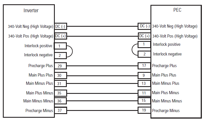
NOTITIE: Verwijs naar de Eaton Hybrid Component en aansluiting Plaats voor Connector Locaties in MY08 Systems
[/fusion_text][/fusion_builder_column][fusion_builder_column type=”1_1″ layout=”1_1″ spacing=”” center_content=”no” link=”” target=”_self” min_height=”” hide_on_mobile=”small-visibility,medium-visibility,large-visibility” class=”” id=”” background_color=”” background_image=”” background_image_id=”” background_position=”left top” background_repeat=”no-repeat” hover_type=”none” border_size=”0″ border_color=”” border_style=”solid” border_position=”all” padding_top=”” padding_right=”” padding_bottom=”” padding_left=”” margin_top=”” margin_bottom=”” animation_type=”” animation_direction=”left” animation_speed=”0.3″ animation_offset=”” last=”no”][fusion_imageframe image_id=”14666|full” max_width=”” style_type=”” blur=”” stylecolor=”” hover_type=”none” bordersize=”” bordercolor=”” borderradius=”” align=”center” lightbox=”no” gallery_id=”” lightbox_image=”” lightbox_image_id=”” alt=”Inverter PEC connectors Eaton Fuller Hybrid transmission” link=”” linktarget=”_self” hide_on_mobile=”small-visibility,medium-visibility,large-visibility” class=”” id=”” animation_type=”” animation_direction=”left” animation_speed=”0.3″ animation_offset=””]https://www.globaltransmissionsupply.com/wp-content/uploads/Inverter-PEC-connectors.png[/fusion_imageframe][/fusion_builder_column][/fusion_builder_row][/fusion_builder_container][fusion_builder_container hundred_percent=”no” hundred_percent_height=”no” hundred_percent_height_scroll=”no” hundred_percent_height_center_content=”yes” equal_height_columns=”no” menu_anchor=”” hide_on_mobile=”small-visibility,medium-visibility,large-visibility” status=”published” publish_date=”” class=”” id=”” background_color=”” background_image=”” background_position=”center center” background_repeat=”no-repeat” fade=”no” background_parallax=”none” enable_mobile=”no” parallax_speed=”0.3″ video_mp4=”” video_webm=”” video_ogv=”” video_url=”” video_aspect_ratio=”16:9″ video_loop=”yes” video_mute=”yes” video_preview_image=”” border_size=”” border_color=”” border_style=”solid” margin_top=”” margin_bottom=”” padding_top=”” padding_right=”” padding_bottom=”” padding_left=””][fusion_builder_row][fusion_builder_column type=”1_1″ layout=”1_1″ spacing=”” center_content=”no” link=”” target=”_self” min_height=”” hide_on_mobile=”small-visibility,medium-visibility,large-visibility” class=”” id=”” background_color=”” background_image=”” background_image_id=”” background_position=”left top” background_repeat=”no-repeat” hover_type=”none” border_size=”0″ border_color=”” border_style=”solid” border_position=”all” padding_top=”” padding_right=”” padding_bottom=”” padding_left=”” margin_top=”” margin_bottom=”” animation_type=”” animation_direction=”left” animation_speed=”0.3″ animation_offset=”” last=”no”][fusion_modal name=”warnings_cautions” title=”waarschuwingen & waarschuwingen” size=”large” background=”” border_color=”” show_footer=”yes” class=”” id=””]Gevaar: Gevaar betekent zult u ernstig gewond raken of gedood als niet de aangegeven procedure niet volgen.
Waarschuwing: Waarschuwing duidt op een onmiddellijk gevaar, die kan leiden tot ernstig persoonlijk letsel als je niet de aangegeven procedure te volgen.
Voorzichtigheid: Let op geeft voertuig of materiële schade zou kunnen ontstaan als je niet de aangegeven procedure te volgen.
Notitie: Note geeft bijkomende details die helpen bij de diagnose of reparatie van een onderdeel / systeem.
Volg de voorgeschreven procedures in de aangegeven volgorde om persoonlijk letsel te voorkomen:
1. Als het hoogspanningsnet kegels zijn rond het voertuig en de lock-out is geïnstalleerd op de PEC, de enige persoon die moet worden toegestaan om het voertuig te starten is de persoon die de lockout tag ondertekend.
2. Voor werkzaamheden aan een voertuig of de cabine te verlaten, terwijl de motor loopt, moet u de versnellingspook in “N” plaatsen trek de handrem, en blokkeren de wielen.
3. Voor veiligheidsredenen, altijd de bedrijfsremmen aangrijpen vóór selectie schakelstanden van “N.”
4. Voordat u begint met een voertuig altijd zitten in de bestuurdersstoel, Selecteer “N” op de schakelbesturingsinrichting, en stel de handrem.
5. In voertuigen met EPTO, de motor en / of
Motor / Generator kan starten in EPTO modus. Voer nooit onderhoud of werken aan het voertuig, In deze modus.
6. 12-Volt batterij positief (+) en negatieve (-) moet vooraf worden losgekoppeld laswerkzaamheden op een hybride voertuig uitgerust.
Voorzichtigheid: Volg de voorgeschreven procedures in de aangegeven volgorde om apparatuur storingen of schade te voorkomen.
Voorzichtigheid: Laat de parkeerrem niet vrijgeven of een poging om een versnelling te selecteren totdat de luchtdruk op het juiste niveau.
Voorzichtigheid: Om beschadiging van de transmissie tijdens het slepen plaats de schakelhefboom in “N” te vermijden en til de aandrijfwielen van de grond en koppel de aandrijflijn.
High-Voltage Waarschuwingen & waarschuwingen
- Gebruik CO2 of Dry Chemical Brandblussers.
- De hoogspanning bedrading bedekt met oranje isolatie of gekronkelde slangen en aangegeven met waarschuwingen op de connectoren.
- Alle Eaton® Hybride Diesel / Elektrische voertuigen zullen worden gemarkeerd als ‘Hybrid’ aan de buitenzijde van het voertuig, samen met de verschuiving label op het dashboard.
- Raadpleeg OEM voor specifieke locatie van het chassis gemonteerde hybridecomponenten.
- Knip niet in de oranje hoogspanningskabels.
- Niet snijden in of open de PEC.
- Knip niet in of de DC / DC-converter te openen.
- Niet snijden in of open de Inverter.
Een bufferzone moet worden opgezet en hoogspanningsinstallaties geïsoleerde rubberhandschoenen (klasse 0 met lederen beschermers) zijn voorafgaand moeten aan hoogspanning. Het negeren van deze instructies kan leiden tot ernstig persoonlijk letsel of de dood.
De rubber isolerende handschoenen die moeten worden gedragen tijdens het werken op de high-voltage systeem zijn klasse 0 met lederen beschermers. De rubberen handschoenen moeten worden getest voor elk gebruik na de rubberen isolatie handschoenen testprocedure vinden in “Diagnostic Tools / Dienst Publicaties” op pagina 6. Het negeren van deze instructies kan leiden tot ernstig persoonlijk letsel of de dood.
Voordat het inspecteren of werken op elk hoogspanningskabels of onderdelen van het “High-Voltage service Shutdown en Power-Up procedure” op pagina 4 moet worden gevolgd. Het negeren van deze instructies kan leiden tot ernstig persoonlijk letsel of de dood.
De Lockout en Tagout apparaten mag alleen worden verwijderd door de technicus die de Lockout en Tagout op het voertuig geplaatst. Het negeren van deze instructies kan leiden tot ernstig persoonlijk letsel of de dood.
Hoogspanning rubber isolerende handschoenen (klasse 0 met lederen beschermers) moet gedragen worden bij het werken op een
hoogspanningskabels. De “High-Voltage service Shutdown en Power-Up procedure” op pagina 4 moet voor worden gevolgd om het verwijderen van hoogspanningskabels. Het negeren van deze instructies kan leiden tot ernstig persoonlijk letsel of de dood.
Hoogspanningskabels en bedrading zijn oranje en voorzien van een waarschuwingslabel op de connectoren. Hoogspanningsonderdelen worden gemarkeerd met een label. Hoogspanning rubber isolerende handschoenen (klasse 0 met lederen beschermers) moeten worden bij het werken op een van deze componenten. Het negeren van deze instructies kan leiden tot ernstig persoonlijk letsel of de dood.
High-Voltage Dienst Uitschakelprocedures

1. Volg de “High-Voltage Work Area” -procedure.
2. Zoek de rode PEC Dienst Switch aan de voorzijde van de PEC en druk uit te schakelen.
3. Verwijder de Dienst Switch Cover en installeer de Lockout Bracket (J48506).
4. Bevestig tag aan de Lockout Bracket.
5. Zorg ervoor dat de PEC Dienst Switch kan niet verplaatsen van de uit-stand.
6. Laat het systeem in te stellen voor een minimum van 5 minuten hoogspanningsontlading.
7. Sluit ServiceRanger en bekijk de Data Monitor PID 116 genaamd “High-Voltage Potential Battery.” Gebruik SPN 520323 voor J1939 aansluiting “Battery Voltage RB” (relaiskast).
8. De spanning moet 30 volt of minder. Indien de spanning boven 30 volt, werken niet op het voertuig en neem contact op Eaton® bij 1-800-826-HELP (4357).
9. Draai de contactsleutel uit en ga verder met repareren of stap het oplossen van problemen.
Notitie: De spanning daalt tot nul wanneer de sleutel uit.
High-Voltage dienst Power-Up Procedure
1. Installeer alle high-voltage connectoren in hun vergrendelde positie.
2. Als je de persoon die werkzaamheden aan het voertuig, verwijder de Lockout Bracket en tag.
3. Installeer de Lockout beugel over de Dienst Switch.
4. Trek de Dienst Schakel uit en laat het voertuig set voor 2 notulen.
5. Start vehicle when appropriate.[/fusion_modal][fusion_modal name=”component_location” title=”Eaton Hybrid Component en aansluiting Plaats ” size=”large” background=”#ffffff” border_color=”” show_footer=”yes” class=”” id=””]

[/fusion_modal][fusion_modal name=”component_location2″ title=”Eaton Hybrid Component en aansluiting Plaats MY09 Systems” size=”large” background=”#ffffff” border_color=”” show_footer=”yes” class=”” id=””]

[/fusion_modal][/fusion_builder_column][/fusion_builder_row][/fusion_builder_container][fusion_builder_container hundred_percent=”no” hundred_percent_height=”no” hundred_percent_height_scroll=”no” hundred_percent_height_center_content=”yes” equal_height_columns=”no” menu_anchor=”” hide_on_mobile=”small-visibility,medium-visibility,large-visibility” status=”published” publish_date=”” class=”” id=”” background_color=”” background_image=”” background_position=”center center” background_repeat=”no-repeat” fade=”no” background_parallax=”none” enable_mobile=”no” parallax_speed=”0.3″ video_mp4=”” video_webm=”” video_ogv=”” video_url=”” video_aspect_ratio=”16:9″ video_loop=”yes” video_mute=”yes” video_preview_image=”” border_size=”” border_color=”” border_style=”solid” margin_top=”” margin_bottom=”” padding_top=”” padding_right=”” padding_bottom=”” padding_left=””][fusion_builder_row][fusion_builder_column type=”1_1″ layout=”1_1″ spacing=”” center_content=”no” link=”” target=”_self” min_height=”” hide_on_mobile=”small-visibility,medium-visibility,large-visibility” class=”” id=”” background_color=”” background_image=”” background_image_id=”” background_position=”left top” background_repeat=”no-repeat” hover_type=”none” border_size=”0″ border_color=”” border_style=”solid” border_position=”all” padding_top=”” padding_right=”” padding_bottom=”” padding_left=”” margin_top=”” margin_bottom=”” animation_type=”” animation_direction=”left” animation_speed=”0.3″ animation_offset=”” last=”no”][fusion_content_boxes layout=”clean-horizontal” columns=”2″ title_size=”18px” heading_size=”3″ title_color=”#ffffff” body_color=”#ffffff” backgroundcolor=”#4f4f4f” icon=”” iconflip=”” iconrotate=”” iconspin=”no” iconcolor=”” icon_circle=”” icon_circle_radius=”” circlecolor=”” circlebordersize=”” circlebordercolor=”” outercirclebordersize=”” outercirclebordercolor=”” icon_size=”” icon_hover_type=”” hover_accent_color=”” image=”” image_id=”” image_width=”” image_height=”” link_type=”” button_span=”” link_area=”” link_target=”” icon_align=”left” animation_type=”” animation_delay=”” animation_offset=”” animation_direction=”left” animation_speed=”0.3″ margin_top=”” margin_bottom=”” hide_on_mobile=”small-visibility,medium-visibility,large-visibility” class=”” id=””][fusion_content_box title=”STAP 1. Verifiëren onderhavige FMIS.” backgroundcolor=”” icon=”” iconflip=”” iconrotate=”” iconspin=”no” iconcolor=”” circlecolor=”” circlebordersize=”” circlebordercolor=”” outercirclebordersize=”” outercirclebordercolor=”” image=”” image_id=”” image_width=”” image_height=”” link=”” linktext=”Lees verder” link_target=”” animation_type=”” animation_direction=”left” animation_speed=”0.3″ animation_offset=””]
- Herzien en volg de waarschuwingen & waarschuwingen.
- Ophalen Actieve foutcodes en FMIS met ServiceRanger met behulp van de 9-polige diagnose-aansluiting.
Gevaar: Zien High-Voltage service Shutdown en Power-Up Procedures. Volg de procedures om schokken te voorkomen, branden of overlijden als gevolg van onjuist gebruik high-voltage. - Welke FMIS aanwezig zijn
- Als Fault Code 116 IMF 14 is genoteerd, ga dan naar stap 9.
- Als Fault Code 116 IMF 10 is genoteerd, ga dan naar stap 2.
- If no Fault Codes are listed, The Service Switch was pushed in. Ga naar stap 10.
[/fusion_content_box][fusion_content_box title=”STAP 2. Verify Data Monitor parameters.” backgroundcolor=”” icon=”” iconflip=”” iconrotate=”” iconspin=”no” iconcolor=”” circlecolor=”” circlebordersize=”” circlebordercolor=”” outercirclebordersize=”” outercirclebordercolor=”” image=”” image_id=”” image_width=”” image_height=”” link=”” linktext=”Lees verder” link_target=”” animation_type=”” animation_direction=”left” animation_speed=”0.3″ animation_offset=””]
- sleutel op.
- Sluit ServiceRanger naar de 9-Way diagnose-aansluiting in de cabine.
- Selecteer de optie “Data Monitor”.
- View the Battery Pack Voltage (BCU1) PID 118 in the high- voltage Battery list:
- If the Battery Pack Voltage (BCU1) PID 118 is greater than 200 volt, ga dan naar stap 3.
- If the Battery Pack Voltage (BCU1) PID 118 is minder dan 200 volt, Vervang de Power Electronics Carrier (PEC), ga dan naar stap 10.
[/fusion_content_box][/fusion_content_boxes][fusion_content_boxes layout=”clean-horizontal” columns=”2″ title_size=”18px” heading_size=”3″ title_color=”#ffffff” body_color=”#ffffff” backgroundcolor=”#4f4f4f” icon=”” iconflip=”” iconrotate=”” iconspin=”no” iconcolor=”” icon_circle=”” icon_circle_radius=”” circlecolor=”” circlebordersize=”” circlebordercolor=”” outercirclebordersize=”” outercirclebordercolor=”” icon_size=”” icon_hover_type=”” hover_accent_color=”” image=”” image_id=”” image_width=”” image_height=”” link_type=”” button_span=”” link_area=”” link_target=”” icon_align=”left” animation_type=”” animation_delay=”” animation_offset=”” animation_direction=”left” animation_speed=”0.3″ margin_top=”” margin_bottom=”” hide_on_mobile=”small-visibility,medium-visibility,large-visibility” class=”” id=””][fusion_content_box title=”STAP 3. Verify continuity of Inverter connector circuits.” backgroundcolor=”” icon=”” iconflip=”” iconrotate=”” iconspin=”no” iconcolor=”” circlecolor=”” circlebordersize=”” circlebordercolor=”” outercirclebordersize=”” outercirclebordercolor=”” image=”” image_id=”” image_width=”” image_height=”” link=”” linktext=”Lees verder” link_target=”” animation_type=”” animation_direction=”left” animation_speed=”0.3″ animation_offset=””]
- Key off.
- If the vehicle is not equipped with a DC/DC Converter or APG, skip this step.
- Using ASTM Class 0 electrical insulating rubber gloves with leather protectors, disconnect the DC cable for the DC/DC Converter and APG at the PEC.
- With the key off, temporarily remove the Lockout Bracket and pull the Service Switch out.
- sleutel op.
- Is Fault Code 116 IMF 10 still Active in ServiceRanger?
- Als Fault Code 116 IMF 10 is Active with the DC/DC Converter and APG disconnected, ga dan naar stap 4.
- Als Fault Code 116 IMF 10 is no longer Active with the DC/DC Converter and APG disconnected, key off and reinstall the Lockout Bracket on the PEC. Replace the Power Electronics Carrier (PEC), ga dan naar stap 10.
[/fusion_content_box][fusion_content_box title=”STAP 4. Verify continuity of PEC connector circuits to ground.” backgroundcolor=”” icon=”” iconflip=”” iconrotate=”” iconspin=”” iconcolor=”” circlecolor=”” circlebordersize=”” circlebordercolor=”” outercirclebordersize=”” outercirclebordercolor=”” image=”” image_id=”” image_width=”” image_height=”” link=”” linktext=”” link_target=”” animation_type=”” animation_direction=”left” animation_speed=”0.3″ animation_offset=””]
- Key off.
- Koppel de PEC 19-polige stekker.
- Temporarily remove the Lockout Bracket and pull the Service Switch out.
Notitie: Ensure the Key Switch is off. - Measure resistance at the PEC 19-Way Connector Terminal at the following pins:
- Pin 17 vastpinnen 19
- Pin 9 vastpinnen 11
- Pin 13 vastpinnen 15
- If the resistance between Pins 17 en Pin 19 is 112-122 ohm en de weerstand van Pin 9 vastpinnen 11 en Pin 13 vastpinnen 15 elk 33-37 ohm, ga dan naar stap 5.
- Als de weerstand buiten bereik, ga dan naar stap 6.
[/fusion_content_box][/fusion_content_boxes][fusion_content_boxes layout=”clean-horizontal” columns=”2″ title_size=”18px” heading_size=”3″ title_color=”#ffffff” body_color=”#ffffff” backgroundcolor=”#4f4f4f” icon=”” iconflip=”” iconrotate=”” iconspin=”no” iconcolor=”” icon_circle=”” icon_circle_radius=”” circlecolor=”” circlebordersize=”” circlebordercolor=”” outercirclebordersize=”” outercirclebordercolor=”” icon_size=”” icon_hover_type=”” hover_accent_color=”” image=”” image_id=”” image_width=”” image_height=”” link_type=”” button_span=”” link_area=”” link_target=”” icon_align=”left” animation_type=”” animation_delay=”” animation_offset=”” animation_direction=”left” animation_speed=”0.3″ margin_top=”” margin_bottom=”” hide_on_mobile=”small-visibility,medium-visibility,large-visibility” class=”” id=””][fusion_content_box title=”STAP 5. Verify continuity of Inverter connector circuits to ground.” backgroundcolor=”” icon=”” iconflip=”” iconrotate=”” iconspin=”no” iconcolor=”” circlecolor=”” circlebordersize=”” circlebordercolor=”” outercirclebordersize=”” outercirclebordercolor=”” image=”” image_id=”” image_width=”” image_height=”” link=”” linktext=”Lees verder” link_target=”” animation_type=”” animation_direction=”left” animation_speed=”0.3″ animation_offset=””]
- Key off.
- Reconnect the PEC 19-Way Connector.
- Koppel de omvormer 56-polige stekker.
- Inspect the connector pins for damaged, corroded and/or loose wires.
- Measure resistance between the Inverter 56-Way Connector at the following pins:
- Pin 29 vastpinnen 37
- Pin 30 vastpinnen 35
- Pin 31 vastpinnen 36 Notitie: Buig Omvormer 56-polige stekker Harness nabij de aansluiting onder het bewaken van de weerstandswaarden.
- Als de weerstand tussen Pin 29 en Pin 37 is 112-122 ohm en de weerstand van Pin 30 vastpinnen 35 en Pin 31 vastpinnen 36 elk 33-37 ohm, push the Service Switch on the PEC and reinstall the Lockout Bracket. Ga naar stap 8.
- Als de weerstand buiten bereik, repair the Hybrid Harness between the PEC and Inverter, ga dan naar stap 10.
[/fusion_content_box][fusion_content_box title=”STAP 6. Verify continuity of PEC connector circuits.” backgroundcolor=”” icon=”” iconflip=”” iconrotate=”” iconspin=”” iconcolor=”” circlecolor=”” circlebordersize=”” circlebordercolor=”” outercirclebordersize=”” outercirclebordercolor=”” image=”” image_id=”” image_width=”” image_height=”” link=”” linktext=”” link_target=”” animation_type=”” animation_direction=”left” animation_speed=”0.3″ animation_offset=””]
- Key off.
- Remove the Air Filter Cover and Air Filter from the PEC. Refer to TRSM1000 for procedures.*
- An Inertia Switch is located at the front of the PEC inside the box and viewable when the Air Filter is removed.
- Using ASTM Class 0 electrical insulating rubber gloves with leather protectors, press the button on the top of the Inertia Switch until heard or felt a click. This switch must be depressed a set distance to reset the switch.
- Measure resistance at the PEC 19-Way Connector Terminal at the following pins:
- Pin 17 vastpinnen 19
- Pin 9 vastpinnen 11
- Pin 13 vastpinnen 15
- qIf the resistance between Pin 17 en Pin 19 is 112-122 ohm en de weerstand van Pin 9 vastpinnen 11 en Pin 13 vastpinnen 15 elk 33-37 ohm, the Inertia Switch was tripped. Test is complete. Ga naar stap 10.
- Als de weerstand buiten bereik, push in the Service Switch on the PEC and reinstall the Lockout Bracket, ga dan naar stap 7.
[/fusion_content_box][/fusion_content_boxes][fusion_content_boxes layout=”clean-horizontal” columns=”2″ title_size=”18px” heading_size=”3″ title_color=”#ffffff” body_color=”#ffffff” backgroundcolor=”#4f4f4f” icon=”” iconflip=”” iconrotate=”” iconspin=”no” iconcolor=”” icon_circle=”” icon_circle_radius=”” circlecolor=”” circlebordersize=”” circlebordercolor=”” outercirclebordersize=”” outercirclebordercolor=”” icon_size=”” icon_hover_type=”” hover_accent_color=”” image=”” image_id=”” image_width=”” image_height=”” link_type=”” button_span=”” link_area=”” link_target=”” icon_align=”left” animation_type=”” animation_delay=”” animation_offset=”” animation_direction=”left” animation_speed=”0.3″ margin_top=”” margin_bottom=”” hide_on_mobile=”small-visibility,medium-visibility,large-visibility” class=”” id=””][fusion_content_box title=”STAP 7. Verify continuity of Inverter connector circuits.” backgroundcolor=”” icon=”” iconflip=”” iconrotate=”” iconspin=”no” iconcolor=”” circlecolor=”” circlebordersize=”” circlebordercolor=”” outercirclebordersize=”” outercirclebordercolor=”” image=”” image_id=”” image_width=”” image_height=”” link=”” linktext=”Lees verder” link_target=”” animation_type=”” animation_direction=”left” animation_speed=”0.3″ animation_offset=””]
- Key off.
- Disconnect the DC High-Voltage Cable at the PEC Bulkhead and at the Inverter Bulkhead.
- Measure resistance between the Low-Voltage Interlock Pins on the PEC side of the DC High-Voltage Cable:
Notitie: The Interlock Pins are the two small spade terminals located in the same opening.- If the resistance is 0–0.3 ohms between the Interlock Loop Pins, Vervang de Power Electronics Carrier (PEC), ga dan naar stap 10.
- Als de weerstand buiten bereik, vervang de DC hoogspanningskabel, ga dan naar stap 10.
[/fusion_content_box][fusion_content_box title=”STAP 8. Verify continuity of DC Cable from PEC to Inverter Connector circuits.” backgroundcolor=”” icon=”” iconflip=”” iconrotate=”” iconspin=”” iconcolor=”” circlecolor=”” circlebordersize=”” circlebordercolor=”” outercirclebordersize=”” outercirclebordercolor=”” image=”” image_id=”” image_width=”” image_height=”” link=”” linktext=”” link_target=”” animation_type=”” animation_direction=”left” animation_speed=”0.3″ animation_offset=””]
- Key off.
- Disconnect the DC High-Voltage Cable at the PEC Bulkhead and the Inverter Bulkhead.
- Measure the resistance of each high-voltage circuit on the cable:
- If the resistance of each high-voltage circuit in the cable is 1 ohm of minder, vervang de Inverter, ga dan naar stap 10.
- Als de weerstand buiten bereik, replace the DC High-Voltage Cable, ga dan naar stap 10.
[/fusion_content_box][/fusion_content_boxes][fusion_content_boxes layout=”clean-horizontal” columns=”2″ title_size=”18px” heading_size=”3″ title_color=”#ffffff” body_color=”#ffffff” backgroundcolor=”#4f4f4f” icon=”” iconflip=”” iconrotate=”” iconspin=”no” iconcolor=”” icon_circle=”” icon_circle_radius=”” circlecolor=”” circlebordersize=”” circlebordercolor=”” outercirclebordersize=”” outercirclebordercolor=”” icon_size=”” icon_hover_type=”” hover_accent_color=”#f41000″ image=”” image_id=”” image_width=”” image_height=”” link_type=”” button_span=”” link_area=”” link_target=”” icon_align=”left” animation_type=”” animation_delay=”” animation_offset=”” animation_direction=”left” animation_speed=”0.3″ margin_top=”” margin_bottom=”” hide_on_mobile=”small-visibility,medium-visibility,large-visibility” class=”” id=””][fusion_content_box title=”STAP 9. Verify Data Monitor parameters.” backgroundcolor=”” icon=”” iconflip=”” iconrotate=”” iconspin=”” iconcolor=”” circlecolor=”” circlebordersize=”” circlebordercolor=”” outercirclebordersize=”” outercirclebordercolor=”” image=”” image_id=”” image_width=”” image_height=”” link=”” linktext=”” link_target=”” animation_type=”” animation_direction=”left” animation_speed=”0.3″ animation_offset=””]
- Sluit ServiceRanger naar de 9-Way diagnose-aansluiting in de cabine.
- Selecteer de optie “Data Monitor”.
- View the following parameters in the High-Voltage Battery list.
- Battery Pack Voltage (BCU1) PID 118
- Battery Voltage PID 116
- If the voltage readings on PID 116 en PID 118 are within 10 volts elkaar, Vervang de Power Electronics Carrier (PEC), ga dan naar stap 10.
- If the voltage readings on PID 116 en PID 118 are greater than 10 volts elkaar, vervang de Inverter, ga dan naar stap 10.
[/fusion_content_box][fusion_content_box title=”STAP 10. Controleer of reparatie.” backgroundcolor=”” icon=”” iconflip=”” iconrotate=”” iconspin=”no” iconcolor=”” circlecolor=”” circlebordersize=”” circlebordercolor=”” outercirclebordersize=”” outercirclebordercolor=”” image=”” image_id=”” image_width=”” image_height=”” link=”” linktext=”Lees verder” link_target=”” animation_type=”” animation_direction=”left” animation_speed=”0.3″ animation_offset=””]
- Key off.
- Sluit alle connectors en de negatieve accukabel.
- sleutel op.
- Clear codes, zien Clear Inactieve Storingen.
- Het voertuig rijdt en probeer de code opnieuw in te stellen.
- Controleer op codes, zien Toon actieve en inactieve Storingen.
- Als er geen codes, test is voltooid.
- Als Fault Code 116 komt naar voren, neem contact op met Eaton op 1- 800-826-HELPEN (4357). Repeat this Step (Stap 10).
- Als een code anders dan 116 komt naar voren, zien Storing Code Index List.
[/fusion_content_box][/fusion_content_boxes][/fusion_builder_column][/fusion_builder_row][/fusion_builder_container][fusion_global id=”13788″]