[fusion_builder_container hundred_percent=nohundred_percent_height=nohundred_percent_height_scroll=nohundred_percent_height_center_content=yesequal_height_columns=nomenu_anchor=”” hide_on_mobile=small-visibility,medium-visibility,large-visibilitystatus=publishedpublish_date=”” class=”” id=”” background_color=”” background_image=”” background_position=center centerbackground_repeat=no-repeatfade=nobackground_parallax=noneenable_mobile=noparallax_speed=”0.3″ video_mp4=”” video_webm=”” video_ogv=”” video_url=”” video_aspect_ratio=”16:9″ video_loop=yesvideo_mute=yesvideo_preview_image=”” border_size=”” border_color=”” border_style=solidmargin_top=”35″ margin_bottom=”” padding_top=”” padding_right=”” padding_bottom=”” padding_left=””][fusion_builder_row][fusion_builder_column type=”1_1layout=”1_1spacing=”” center_content=nolink=”” target=_selfmin_height=”” hide_on_mobile=small-visibility,medium-visibility,large-visibilityclass=”” id=”” background_color=”” background_image=”” background_image_id=”” background_position=left topbackground_repeat=no-repeathover_type=noneborder_size=”0″ border_color=”” border_style=solidborder_position=allpadding_top=”” padding_right=”” padding_bottom=”” padding_left=”” margin_top=”” margin_bottom=”” animation_type=”” animation_direction=leftanimation_speed=”0.3″ animation_offset=”” last=no”][fusion_text columns=”” column_min_width=”” column_spacing=”” rule_style=defaultrule_size=”” rule_color=”” hide_on_mobile=small-visibility,medium-visibility,large-visibilityclass=”” id=””]

イートンフラーハイブリッドトランスミッションフォルトコード 116 – 高電圧リレー -(MY08システム)

[/fusion_text][/fusion_builder_column][/fusion_builder_row][/fusion_builder_container][fusion_builder_container hundred_percent=nohundred_percent_height=nohundred_percent_height_scroll=nohundred_percent_height_center_content=yesequal_height_columns=nomenu_anchor=”” hide_on_mobile=small-visibility,medium-visibility,large-visibilitystatus=publishedpublish_date=”” class=”” id=”” background_color=”” background_image=”” background_position=center centerbackground_repeat=no-repeatfade=nobackground_parallax=noneenable_mobile=noparallax_speed=”0.3″ video_mp4=”” video_webm=”” video_ogv=”” video_url=”” video_aspect_ratio=”16:9″ video_loop=yesvideo_mute=yesvideo_preview_image=”” border_size=”” border_color=”” border_style=solidmargin_top=”” margin_bottom=”” padding_top=”” padding_right=”” padding_bottom=”” padding_left=””][fusion_builder_row][fusion_builder_column type=”1_1layout=”1_1spacing=”” center_content=nolink=”” target=_selfmin_height=”” hide_on_mobile=small-visibility,medium-visibility,large-visibilityclass=”” id=”” background_color=”” background_image=”” background_image_id=”” background_position=left topbackground_repeat=no-repeathover_type=noneborder_size=”0″ border_color=”” border_style=solidborder_position=allpadding_top=”” padding_right=”” padding_bottom=”” padding_left=”” margin_top=”” margin_bottom=”” animation_type=”” animation_direction=leftanimation_speed=”0.3″ animation_offset=”” last=no”][fusion_text columns=”” column_min_width=”” column_spacing=”” rule_style=defaultrule_size=”” rule_color=”” hide_on_mobile=small-visibility,medium-visibility,large-visibilityclass=”” id=””]

イートンハイブリッド駆動システムモデルのフォルトコード (MY08) EH-8E306A-U, EH-8E306A-UPG, EH-8E306A-UP, EH-8E306A-CD, EH-8E306A-T, EH-6E606B-CD. テストする方法を学ぶために以下をお読み, はっきりと自分のフレイトライナーのフォルトコードのエラーを修正, マック, ピータービルト, ケンワース, ボルボ, 国際, そして、大型トラックおよび機器. The High-Voltage Relays are located inside the Power Electronics Carrier (PEC) リレーボックス単位で. There is 1 precharge relay on the positive side, プラス側の追加リレー, そして 1 on the negative for a total of 3. システムがオフのときにこれらのリレーは、通常は開いています. リレーは、インバータを介して制御されています.

コードの障害 116 – High Voltage Relays Detection

システムが障害を検出する前に、次の前提条件が満たされなければなりません:

  • インバータ点火電圧がより大きく、 7 ボルト未満 16 ボルト.

注意: 非アクティブコードのトラブルシューティングを行う際に参照してください。 製品診断モード (PDM)

活断層コードを設定するための条件

  • 国際通貨基金 10 is set when the Inverter detects the input voltage measured at the capacitor is less than 210 volts within 3 seconds after the sub-relay closed in the Relay Box.
  • 国際通貨基金 14 is set when only the negative relay in the Relay Box is on and capacitor voltage decreases less than 10 volts/5 seconds when initial capacitor voltage was greater than 200 volts and motor speed less than 500 min-1, or there is a detect error in the initial check.

フォールバックするとフォルトコード 116 以下の条件が発生しています:

  • FMIのためのアンバー「チェック・ハイブリッド」ランプが点滅 10 and remains solid for FMI 14.
  • 障害は、HCMのメモリに記憶されています.
  • インバータは、高電圧システムを遮断します.
  • HCMは、ディーゼル専用モードでハイブリッド車両を制御するために継続します.
  • 送信のデフォルトは第一に、ギアを開始します.

[/fusion_text][fusion_text columns=”” column_min_width=”” column_spacing=”” rule_style=defaultrule_size=”” rule_color=”” hide_on_mobile=small-visibility,medium-visibility,large-visibilityclass=”” id=””]

フォルトコード非アクティブを設定するための条件

のみ非アクティブな障害はトランスミッション電子制御ユニットからクリアすることができます (TECU) ServiceRangerを使用して、またはHCMの歴史. TECUは後に自動的に履歴から障害をクリア 200 時間や障害が非アクティブになった後HCMは自動的に履歴から障害をクリアします 200 時間.

この障害コードは、次のいずれかが原因で発生することができ:

  • 国際通貨基金 10
    • PEC
    • APG
    • インバーター
    • DC high-voltage cable
    • DC cable interlock loops
    • 慣性スイッチ
    • サービススイッチ
  • 国際通貨基金 14
    • インバーター
    • PEC

[/fusion_text][/fusion_builder_column][/fusion_builder_row][/fusion_builder_container][fusion_builder_container hundred_percent=nohundred_percent_height=nohundred_percent_height_scroll=nohundred_percent_height_center_content=yesequal_height_columns=nomenu_anchor=”” hide_on_mobile=small-visibility,medium-visibility,large-visibilitystatus=publishedpublish_date=”” class=”” id=”” background_color=”” background_image=”” background_position=center centerbackground_repeat=no-repeatfade=nobackground_parallax=noneenable_mobile=noparallax_speed=”0.3″ video_mp4=”” video_webm=”” video_ogv=”” video_url=”” video_aspect_ratio=”16:9″ video_loop=yesvideo_mute=yesvideo_preview_image=”” border_size=”” border_color=”” border_style=solidmargin_top=”” margin_bottom=”” padding_top=”” padding_right=”” padding_bottom=”” padding_left=””][fusion_builder_row][fusion_builder_column type=”1_1layout=”1_1spacing=”” center_content=nolink=”” target=_selfmin_height=”” hide_on_mobile=small-visibility,medium-visibility,large-visibilityclass=”” id=”” background_color=”” background_image=”” background_image_id=”” background_position=left topbackground_repeat=no-repeathover_type=noneborder_size=”0″ border_color=”” border_style=solidborder_position=allpadding_top=”” padding_right=”” padding_bottom=”” padding_left=”” margin_top=”” margin_bottom=”” animation_type=”” animation_direction=leftanimation_speed=”0.3″ animation_offset=”” last=no”][fusion_text columns=”” column_min_width=”” column_spacing=”” rule_style=defaultrule_size=”” rule_color=”” hide_on_mobile=small-visibility,medium-visibility,large-visibilityclass=”” id=””]

コードの障害 116 – High Voltage Relays Test

[/fusion_text][/fusion_builder_column][/fusion_builder_row][/fusion_builder_container][fusion_builder_container hundred_percent=nohundred_percent_height=nohundred_percent_height_scroll=nohundred_percent_height_center_content=yesequal_height_columns=nomenu_anchor=”” hide_on_mobile=small-visibility,medium-visibility,large-visibilitystatus=publishedpublish_date=”” class=”” id=”” background_color=”” background_image=”” background_position=center centerbackground_repeat=no-repeatfade=nobackground_parallax=noneenable_mobile=noparallax_speed=”0.3″ video_mp4=”” video_webm=”” video_ogv=”” video_url=”” video_aspect_ratio=”16:9″ video_loop=yesvideo_mute=yesvideo_preview_image=”” border_size=”” border_color=”” border_style=solidmargin_top=”” margin_bottom=”” padding_top=”” padding_right=”” padding_bottom=”” padding_left=””][fusion_builder_row][fusion_builder_column type=”1_1layout=”1_1spacing=”” center_content=nolink=”” target=_selfmin_height=”” hide_on_mobile=small-visibility,medium-visibility,large-visibilityclass=”” id=”” background_color=”” background_image=”” background_image_id=”” background_position=left topbackground_repeat=no-repeathover_type=noneborder_size=”0″ border_color=”” border_style=solidborder_position=allpadding_top=”” padding_right=”” padding_bottom=”” padding_left=”” margin_top=”” margin_bottom=”” animation_type=”” animation_direction=leftanimation_speed=”0.3″ animation_offset=”” last=no”][fusion_text columns=”” column_min_width=”” column_spacing=”” rule_style=defaultrule_size=”” rule_color=”” hide_on_mobile=small-visibility,medium-visibility,large-visibilityclass=”” id=””]

コンポーネントの識別MY08システム:

[/fusion_text][/fusion_builder_column][/fusion_builder_row][/fusion_builder_container][fusion_builder_container hundred_percent=yeshundred_percent_height=nohundred_percent_height_scroll=nohundred_percent_height_center_content=yesequal_height_columns=nomenu_anchor=”” hide_on_mobile=small-visibility,medium-visibility,large-visibilitystatus=publishedpublish_date=”” class=”” id=”” background_color=”” background_image=”” background_position=center centerbackground_repeat=no-repeatfade=nobackground_parallax=noneenable_mobile=noparallax_speed=”0.3″ video_mp4=”” video_webm=”” video_ogv=”” video_url=”” video_aspect_ratio=”16:9″ video_loop=yesvideo_mute=yesvideo_preview_image=”” border_size=”” border_color=”” border_style=solidmargin_top=”” margin_bottom=”” padding_top=”” padding_right=”10%” padding_bottom=”” padding_left=”10%”][fusion_builder_row][fusion_builder_column type=”1_3layout=”1_3spacing=”” center_content=nolink=”” target=_selfmin_height=”” hide_on_mobile=small-visibility,medium-visibility,large-visibilityclass=”” id=”” background_color=”” background_image=”” background_image_id=”” background_position=left topbackground_repeat=no-repeathover_type=noneborder_size=”0″ border_color=”” border_style=solidborder_position=allpadding_top=”” padding_right=”” padding_bottom=”” padding_left=”” margin_top=”” margin_bottom=”” animation_type=”” animation_direction=leftanimation_speed=”0.3″ animation_offset=”” last=no”][fusion_imageframe image_id=”14474|fullmax_width=”” style_type=”” blur=”” stylecolor=”” hover_type=nonebordersize=”” bordercolor=”” borderradius=”” align=centerlightbox=nogallery_id=”” lightbox_image=”” lightbox_image_id=”” alt=”デルファイ56ウェイ嵌合コネクタ見ます” link=”” linktarget=_selfhide_on_mobile=small-visibility,medium-visibility,large-visibilityclass=”” id=”” animation_type=”” animation_direction=leftanimation_speed=”0.3″ animation_offset=””]https://www.globaltransmissionsupply.com/wp-content/uploads/Inverter-56-Way-Mating-Connector-View.jpg[/fusion_imageframe][fusion_text columns=”” column_min_width=”” column_spacing=”” rule_style=defaultrule_size=”” rule_color=”” hide_on_mobile=small-visibility,medium-visibility,large-visibilityclass=”” id=””]

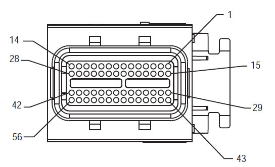
56-ウェイ嵌合コネクタ見ます

[/fusion_text][/fusion_builder_column][fusion_builder_column type=”1_3layout=”1_3spacing=”” center_content=nolink=”” target=_selfmin_height=”” hide_on_mobile=small-visibility,medium-visibility,large-visibilityclass=”” id=”” background_color=”” background_image=”” background_image_id=”” background_position=left topbackground_repeat=no-repeathover_type=noneborder_size=”0″ border_color=”” border_style=solidborder_position=allpadding_top=”” padding_right=”” padding_bottom=”” padding_left=”” margin_top=”” margin_bottom=”” animation_type=”” animation_direction=leftanimation_speed=”0.3″ animation_offset=”” last=no”][fusion_imageframe image_id=”14635|fullmax_width=”” style_type=”” blur=”” stylecolor=”” hover_type=nonebordersize=”” bordercolor=”” borderradius=”” align=centerlightbox=nogallery_id=”” lightbox_image=”” lightbox_image_id=”” alt=”高電圧DCコネクタ見る矢崎コネクタ” link=”” linktarget=_selfhide_on_mobile=small-visibility,medium-visibility,large-visibilityclass=”” id=”” animation_type=”” animation_direction=leftanimation_speed=”0.3″ animation_offset=””]https://www.globaltransmissionsupply.com/wp-content/uploads/High-Voltage-DC-Connector-View.jpg[/fusion_imageframe][fusion_text columns=”” column_min_width=”” column_spacing=”” rule_style=defaultrule_size=”” rule_color=”” hide_on_mobile=small-visibility,medium-visibility,large-visibilityclass=”” id=””]

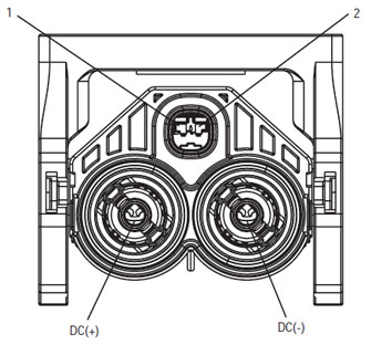
高電圧DCコネクタ見る矢崎コネクタ

[/fusion_text][/fusion_builder_column][fusion_builder_column type=”1_3layout=”1_3spacing=”” center_content=nolink=”” target=_selfmin_height=”” hide_on_mobile=small-visibility,medium-visibility,large-visibilityclass=”” id=”” background_color=”” background_image=”” background_image_id=”” background_position=left topbackground_repeat=no-repeathover_type=noneborder_size=”0″ border_color=”” border_style=solidborder_position=allpadding_top=”” padding_right=”” padding_bottom=”” padding_left=”” margin_top=”” margin_bottom=”” animation_type=”” animation_direction=leftanimation_speed=”0.3″ animation_offset=”” last=no”][fusion_imageframe image_id=”14213|mediummax_width=”” style_type=”” blur=”” stylecolor=”” hover_type=nonebordersize=”” bordercolor=”” borderradius=”” align=centerlightbox=nogallery_id=”” lightbox_image=”” lightbox_image_id=”” alt=Mating Connector View Deutsch 19 – 方法” link=”” linktarget=_selfhide_on_mobile=small-visibility,medium-visibility,large-visibilityclass=”” id=”” animation_type=”” animation_direction=leftanimation_speed=”0.3″ animation_offset=””]https://www.globaltransmissionsupply.com/wp-content/uploads/Eaton-Fuller-Harness-Connector-View-300×289.jpg[/fusion_imageframe][fusion_text columns=”” column_min_width=”” column_spacing=”” rule_style=defaultrule_size=”” rule_color=”” hide_on_mobile=small-visibility,medium-visibility,large-visibilityclass=”” id=””]

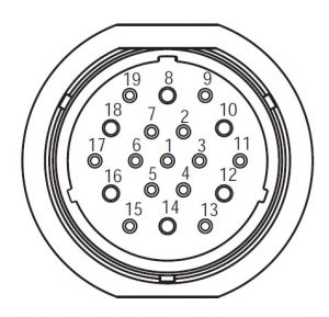
Mating Connector View Deutsch 19 – 方法

[/fusion_text][/fusion_builder_column][/fusion_builder_row][/fusion_builder_container][fusion_builder_container hundred_percent=nohundred_percent_height=nohundred_percent_height_scroll=nohundred_percent_height_center_content=yesequal_height_columns=nomenu_anchor=”” hide_on_mobile=small-visibility,medium-visibility,large-visibilitystatus=publishedpublish_date=”” class=”” id=”” background_color=”” background_image=”” background_position=center centerbackground_repeat=no-repeatfade=nobackground_parallax=noneenable_mobile=noparallax_speed=”0.3″ video_mp4=”” video_webm=”” video_ogv=”” video_url=”” video_aspect_ratio=”16:9″ video_loop=yesvideo_mute=yesvideo_preview_image=”” border_size=”” border_color=”” border_style=solidmargin_top=”” margin_bottom=”” padding_top=”” padding_right=”” padding_bottom=”” padding_left=””][fusion_builder_row][fusion_builder_column type=”1_1layout=”1_1spacing=”” center_content=nolink=”” target=_selfmin_height=”” hide_on_mobile=small-visibility,medium-visibility,large-visibilityclass=”” id=”” background_image_id=”” background_color=”#000000″ background_image=”” background_position=left topundefined=”” background_repeat=no-repeathover_type=noneborder_size=”0″ border_color=”” border_style=solidborder_position=allpadding_top=”” padding_right=”” padding_bottom=”” padding_left=”” margin_top=”” margin_bottom=”” animation_type=”” animation_direction=leftanimation_speed=”0.3″ animation_offset=”” last=no”][fusion_text columns=”” column_min_width=”” column_spacing=”” rule_style=defaultrule_size=”” rule_color=”” hide_on_mobile=small-visibility,medium-visibility,large-visibilityclass=”” id=””]

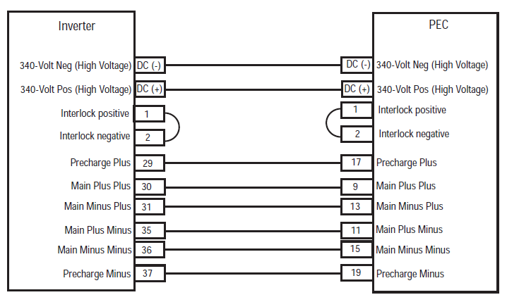
注意: を参照してください。 イートンハイブリッドコンポーネントおよびコネクタの位置 MY08システムでのコネクタの位置については、
[/fusion_text][/fusion_builder_column][fusion_builder_column type=”1_1layout=”1_1spacing=”” center_content=nolink=”” target=_selfmin_height=”” hide_on_mobile=small-visibility,medium-visibility,large-visibilityclass=”” id=”” background_color=”” background_image=”” background_image_id=”” background_position=left topbackground_repeat=no-repeathover_type=noneborder_size=”0″ border_color=”” border_style=solidborder_position=allpadding_top=”” padding_right=”” padding_bottom=”” padding_left=”” margin_top=”” margin_bottom=”” animation_type=”” animation_direction=leftanimation_speed=”0.3″ animation_offset=”” last=no”][fusion_imageframe image_id=”14666|fullmax_width=”” style_type=”” blur=”” stylecolor=”” hover_type=nonebordersize=”” bordercolor=”” borderradius=”” align=centerlightbox=nogallery_id=”” lightbox_image=”” lightbox_image_id=”” alt=Inverter PEC connectors Eaton Fuller Hybrid transmissionlink=”” linktarget=_selfhide_on_mobile=small-visibility,medium-visibility,large-visibilityclass=”” id=”” animation_type=”” animation_direction=leftanimation_speed=”0.3″ animation_offset=””]https://www.globaltransmissionsupply.com/wp-content/uploads/Inverter-PEC-connectors.png[/fusion_imageframe][/fusion_builder_column][/fusion_builder_row][/fusion_builder_container][fusion_builder_container hundred_percent=nohundred_percent_height=nohundred_percent_height_scroll=nohundred_percent_height_center_content=yesequal_height_columns=nomenu_anchor=”” hide_on_mobile=small-visibility,medium-visibility,large-visibilitystatus=publishedpublish_date=”” class=”” id=”” background_color=”” background_image=”” background_position=center centerbackground_repeat=no-repeatfade=nobackground_parallax=noneenable_mobile=noparallax_speed=”0.3″ video_mp4=”” video_webm=”” video_ogv=”” video_url=”” video_aspect_ratio=”16:9″ video_loop=yesvideo_mute=yesvideo_preview_image=”” border_size=”” border_color=”” border_style=solidmargin_top=”” margin_bottom=”” padding_top=”” padding_right=”” padding_bottom=”” padding_left=””][fusion_builder_row][fusion_builder_column type=”1_1layout=”1_1spacing=”” center_content=nolink=”” target=_selfmin_height=”” hide_on_mobile=small-visibility,medium-visibility,large-visibilityclass=”” id=”” background_color=”” background_image=”” background_image_id=”” background_position=left topbackground_repeat=no-repeathover_type=noneborder_size=”0″ border_color=”” border_style=solidborder_position=allpadding_top=”” padding_right=”” padding_bottom=”” padding_left=”” margin_top=”” margin_bottom=”” animation_type=”” animation_direction=leftanimation_speed=”0.3″ animation_offset=”” last=no”][fusion_modal name=warnings_cautionstitle=”警告 & 注意事項” size=largebackground=”” border_color=”” show_footer=yesclass=”” id=””]危険: 危険は指示された手順に従わない場合は、重傷を負ったり殺されることを示します.
警告: 警告は、すぐに危険を示し、, あなたが示された手順に従わない場合には重大な人身事故につながる可能性があります.
あぶない: 注意は、あなたが示された手順に従わない場合は車両や物的損害が発生する可能性を示しています.

注意: 注コンポーネント/システムの診断又は修理に役立つ追加の詳細を示しています.

人身事故を避けるために、指示された順序で指定された手順に従ってください:

1. 高電圧コーンは、車両の周囲にあり、ロックアウトは、PECにインストールされている場合, 車両を発進させるべきである唯一の人はロックアウトタグに署名した人物であります.
2. 車両の作業やタクシーを出る前に、エンジンが実行されている間, あなたは、パーキングブレーキを設定し、「N」にシフトレバーを配置する必要があります, そして、車輪をブロックします.
3. 安全対策のため, 常に「N.」からギアポジションを選択する前に、サービスブレーキを従事
4. 必ず運転席に着席する車両を開始する前に, シフト制御の「N」を選択, そして、パーキングブレーキを設定.
5. EPTO付き車両で, エンジンおよび/または
モータ/発電機はEPTOモードで起動することができます. 車両のメンテナンスや作業を行うことはありません, このモード中.
6. 12-ボルトバッテリー正 (+) そして、負 (-) 任意のハイブリッド車両搭載上の任意の溶接前に切断されなければなりません.

あぶない: 機器の故障や破損を避けるために、指示された順序で指定された手順に従ってください.
あぶない: 空気圧が適正なレベルになるまで、パーキングブレーキを解除したり、ギアを選択しようとしないでください.
あぶない: 「N」にシフトレバーを場所を牽引時の伝送への損傷を避け、地面から駆動輪を持ち上げたり、ドライブラインを切断するには.

高電圧の警告 & 注意事項

  • CO2を使用するか、またはドライケミカル消火器.
  • 高電圧配線はオレンジ絶縁または複雑なチューブで覆われており、コネクタの警告ラベルが付いています.
  • すべてのEaton®ハイブリッドディーゼル/電気自動車は、「ハイブリッドマークされます’ 車両の外側に, ダッシュ上のシフトラベルと一緒に.
  • シャーシ搭載ハイブリッド部品の特定の場所のためにOEMを参照.
  • オレンジ色の高電圧ケーブルに切断しないでください.
  • PECをにカットしたり開いたりしないでください.
  • カットまたはDC / DCコンバータを開けないでください.
  • カットまたはインバータを開けないでください.

バッファゾーンを設定し、高電圧絶縁ゴム手袋されなければなりません (クラス 0 革プロテクター付き) 高電圧で作業する前に必要とされています. これらの指示に従わないと、重大な人身事故や死に至ることが.
高電圧システムで作業しながら、着用しなければならないゴム絶縁手袋はクラスであります 0 革プロテクター付き. ゴム手袋は、ページの「診断ツール/サービス出版物」で見つかったゴム製絶縁手袋の試験手順以下のEVERY使用する前にテストする必要があります 6. これらの指示に従わないと、重大な人身事故や死に至ることが.
ページの「高電圧サービスのシャットダウンとパワーアップ手順」を検査または任意の高電圧ケーブルやコンポーネントの作業を行う前に、 4 従うべきです. これらの指示に従わないと、重大な人身事故や死に至ることが.
ロックアウトとタグアウト装置は、車両にロックアウトとタグアウト装置を配置技術によって除去されなければなりません. これらの指示に従わないと、重大な人身事故や死に至ることが.
高電圧絶縁ゴム手袋 (クラス 0 革プロテクター付き) 任意の上で作業するときに着用しなければなりません
高電圧ケーブル. ページの「高電圧・サービスのシャットダウンとパワーアップ手順」 4 任意の高電圧ケーブルを除去する前に従わなければなりません. これらの指示に従わないと、重大な人身事故や死に至ることが.
高電圧ケーブルや配線がオレンジ色であり、コネクタの警告ラベルが含まれています. 高電圧部品は、ラベルが付いています. 高電圧絶縁ゴム手袋 (クラス 0 革プロテクター付き) これらのコンポーネントのいずれかで作業するときに使用する必要があります. これらの指示に従わないと、重大な人身事故や死に至ることが.

高電圧・サービスのシャットダウン手順

高電圧サービスのシャットダウンとパワーアップ手順1. 「高電圧ワークエリア」の手順に従ってください.
2. PECの前面にある赤いPECサービススイッチの位置を確認し、オフにプッシュします.
3. サービススイッチのカバーを外し、ロックアウトブラケットを取り付けます (J48506).
4. ロックアウトブラケットにタグを固定し.
5. PECサービススイッチがオフの位置から移動することはできません確認してください.
6. システムは最低に設定することを許可します 5 高電圧を放電する分.
7. ServiceRangerを接続し、データモニタPIDを表示 116 「高電圧バッテリポテンシャル」と呼ば使用SPN 520323 J1939接続用の「バッテリー電圧RB」 (リレーボックス).
8. 電圧はする必要があります 30 ボルト以下. 電圧は、上記の場合 30 ボルト, 車両に取り組み、1-800-826-HELPでEaton®接触していません (4357).
9. イグニッションキーをオフにし、修理やトラブルシューティングのステップに進みます.
注意: キーがオフのときの電圧がゼロに低下します.

高電圧サービスパワーアップ手順

1. 彼らのロックされた位置にすべての高電圧コネクタをインストールします。.
2. あなたがいる場合は人が車両に取り組んで, ロックアウトブラケットとタグを削除.
3. サービススイッチ上でロックアウトブラケットを再インストールします.
4. サービスを引っ張り出し切り替えて、車両がために設定しましょう 2 分.
5. Start vehicle when appropriate.[/fusion_modal][fusion_modal name=component_locationtitle=”イートンハイブリッドコンポーネントおよびコネクタの位置 ” size=largebackground=”#ffffffborder_color=”” show_footer=yesclass=”” id=””]

イートンハイブリッドコンポーネントおよびコネクタの位置MY08システム

[/fusion_modal][fusion_modal name=component_location2title=”イートンハイブリッドコンポーネントおよびコネクタの位置MY09システム” size=largebackground=”#ffffffborder_color=”” show_footer=yesclass=”” id=””]

イートンハイブリッドコンポーネントおよびコネクタの位置MY09システム

[/fusion_modal][/fusion_builder_column][/fusion_builder_row][/fusion_builder_container][fusion_builder_container hundred_percent=nohundred_percent_height=nohundred_percent_height_scroll=nohundred_percent_height_center_content=yesequal_height_columns=nomenu_anchor=”” hide_on_mobile=small-visibility,medium-visibility,large-visibilitystatus=publishedpublish_date=”” class=”” id=”” background_color=”” background_image=”” background_position=center centerbackground_repeat=no-repeatfade=nobackground_parallax=noneenable_mobile=noparallax_speed=”0.3″ video_mp4=”” video_webm=”” video_ogv=”” video_url=”” video_aspect_ratio=”16:9″ video_loop=yesvideo_mute=yesvideo_preview_image=”” border_size=”” border_color=”” border_style=solidmargin_top=”” margin_bottom=”” padding_top=”” padding_right=”” padding_bottom=”” padding_left=””][fusion_builder_row][fusion_builder_column type=”1_1layout=”1_1spacing=”” center_content=nolink=”” target=_selfmin_height=”” hide_on_mobile=small-visibility,medium-visibility,large-visibilityclass=”” id=”” background_color=”” background_image=”” background_image_id=”” background_position=left topbackground_repeat=no-repeathover_type=noneborder_size=”0″ border_color=”” border_style=solidborder_position=allpadding_top=”” padding_right=”” padding_bottom=”” padding_left=”” margin_top=”” margin_bottom=”” animation_type=”” animation_direction=leftanimation_speed=”0.3″ animation_offset=”” last=no”][fusion_content_boxes layout=clean-horizontalcolumns=”2″ title_size=”18pxheading_size=”3″ title_color=”#ffffffbody_color=”#ffffffbackgroundcolor=”#4f4f4ficon=”” iconflip=”” iconrotate=”” iconspin=noiconcolor=”” icon_circle=”” icon_circle_radius=”” circlecolor=”” circlebordersize=”” circlebordercolor=”” outercirclebordersize=”” outercirclebordercolor=”” icon_size=”” icon_hover_type=”” hover_accent_color=”” image=”” image_id=”” image_width=”” image_height=”” link_type=”” button_span=”” link_area=”” link_target=”” icon_align=leftanimation_type=”” animation_delay=”” animation_offset=”” animation_direction=leftanimation_speed=”0.3″ margin_top=”” margin_bottom=”” hide_on_mobile=small-visibility,medium-visibility,large-visibilityclass=”” id=””][fusion_content_box title=STEP 1. FMISの存在を確認してください.backgroundcolor=”” icon=”” iconflip=”” iconrotate=”” iconspin=noiconcolor=”” circlecolor=”” circlebordersize=”” circlebordercolor=”” outercirclebordersize=”” outercirclebordercolor=”” image=”” image_id=”” image_width=”” image_height=”” link=”” linktext=”続きを読む” link_target=”” animation_type=”” animation_direction=leftanimation_speed=”0.3″ animation_offset=””]

  1. 確認とフォロー 警告 & 注意事項.
  2. 9ウェイの診断コネクタを使用してServiceRangerと活断層コードとFMISを取得.
    危険: 見る 高電圧・サービスのシャットダウンとパワーアップ手順. ショックを避けるために、手順に従ってください, 不適切な取り扱い高電圧から火傷や死亡.
  3. どのFMIS存在しています
    • フォルトコードの場合 116 国際通貨基金 14 リストされています, 進みます 9.
    • フォルトコードの場合 116 国際通貨基金 10 リストされています, 進みます 2.
    • If no Fault Codes are listed, The Service Switch was pushed in. ステップに進みます。 10.

[/fusion_content_box][fusion_content_box title=STEP 2. Verify Data Monitor parameters.backgroundcolor=”” icon=”” iconflip=”” iconrotate=”” iconspin=noiconcolor=”” circlecolor=”” circlebordersize=”” circlebordercolor=”” outercirclebordersize=”” outercirclebordercolor=”” image=”” image_id=”” image_width=”” image_height=”” link=”” linktext=”続きを読む” link_target=”” animation_type=”” animation_direction=leftanimation_speed=”0.3″ animation_offset=””]

  1. 上のキー.
  2. タクシーで9ウェイの診断コネクタにServiceRangerを接続します.
  3. 「データモニタ」オプションを選択します.
  4. View the Battery Pack Voltage (BCU1) PID 118 in the high- voltage Battery list:
    • If the Battery Pack Voltage (BCU1) PID 118 is greater than 200 ボルト, 進みます 3.
    • If the Battery Pack Voltage (BCU1) PID 118 よりも少ない 200 ボルト, パワーエレクトロニクスキャリアを交換 (PEC), その後に進みます 10.

[/fusion_content_box][/fusion_content_boxes][fusion_content_boxes layout=clean-horizontalcolumns=”2″ title_size=”18pxheading_size=”3″ title_color=”#ffffffbody_color=”#ffffffbackgroundcolor=”#4f4f4ficon=”” iconflip=”” iconrotate=”” iconspin=noiconcolor=”” icon_circle=”” icon_circle_radius=”” circlecolor=”” circlebordersize=”” circlebordercolor=”” outercirclebordersize=”” outercirclebordercolor=”” icon_size=”” icon_hover_type=”” hover_accent_color=”” image=”” image_id=”” image_width=”” image_height=”” link_type=”” button_span=”” link_area=”” link_target=”” icon_align=leftanimation_type=”” animation_delay=”” animation_offset=”” animation_direction=leftanimation_speed=”0.3″ margin_top=”” margin_bottom=”” hide_on_mobile=small-visibility,medium-visibility,large-visibilityclass=”” id=””][fusion_content_box title=STEP 3. Verify continuity of Inverter connector circuits.backgroundcolor=”” icon=”” iconflip=”” iconrotate=”” iconspin=noiconcolor=”” circlecolor=”” circlebordersize=”” circlebordercolor=”” outercirclebordersize=”” outercirclebordercolor=”” image=”” image_id=”” image_width=”” image_height=”” link=”” linktext=”続きを読む” link_target=”” animation_type=”” animation_direction=leftanimation_speed=”0.3″ animation_offset=””]

  1. キーオフ.
  2. If the vehicle is not equipped with a DC/DC Converter or APG, skip this step.
  3. Using ASTM Class 0 electrical insulating rubber gloves with leather protectors, disconnect the DC cable for the DC/DC Converter and APG at the PEC.
  4. With the key off, temporarily remove the Lockout Bracket and pull the Service Switch out.
  5. 上のキー.
  6. フォルトコードは、 116 国際通貨基金 10 still Active in ServiceRanger?
    • フォルトコードの場合 116 国際通貨基金 10 is Active with the DC/DC Converter and APG disconnected, 進みます 4.
    • フォルトコードの場合 116 国際通貨基金 10 is no longer Active with the DC/DC Converter and APG disconnected, key off and reinstall the Lockout Bracket on the PEC. Replace the Power Electronics Carrier (PEC), その後に進みます 10.

[/fusion_content_box][fusion_content_box title=STEP 4. Verify continuity of PEC connector circuits to ground.backgroundcolor=”” icon=”” iconflip=”” iconrotate=”” iconspin=”” iconcolor=”” circlecolor=”” circlebordersize=”” circlebordercolor=”” outercirclebordersize=”” outercirclebordercolor=”” image=”” image_id=”” image_width=”” image_height=”” link=”” linktext=”” link_target=”” animation_type=”” animation_direction=leftanimation_speed=”0.3″ animation_offset=””]

  1. キーオフ.
  2. PEC 19ウェイコネクタを外してください.
  3. Temporarily remove the Lockout Bracket and pull the Service Switch out.
    注意: Ensure the Key Switch is off.
  4. Measure resistance at the PEC 19-Way Connector Terminal at the following pins:
    • ピン 17 ピンへ 19
    • ピン 9 ピンへ 11
    • ピン 13 ピンへ 15
      • If the resistance between Pins 17 そして、ピン 19 112から122オームとピンからの抵抗であります 9 ピンへ 11 そして、ピン 13 ピンへ 15 各33-37オームであります, 進みます 5.
      • 抵抗値は、範囲外の場合, 進みます 6.

[/fusion_content_box][/fusion_content_boxes][fusion_content_boxes layout=clean-horizontalcolumns=”2″ title_size=”18pxheading_size=”3″ title_color=”#ffffffbody_color=”#ffffffbackgroundcolor=”#4f4f4ficon=”” iconflip=”” iconrotate=”” iconspin=noiconcolor=”” icon_circle=”” icon_circle_radius=”” circlecolor=”” circlebordersize=”” circlebordercolor=”” outercirclebordersize=”” outercirclebordercolor=”” icon_size=”” icon_hover_type=”” hover_accent_color=”” image=”” image_id=”” image_width=”” image_height=”” link_type=”” button_span=”” link_area=”” link_target=”” icon_align=leftanimation_type=”” animation_delay=”” animation_offset=”” animation_direction=leftanimation_speed=”0.3″ margin_top=”” margin_bottom=”” hide_on_mobile=small-visibility,medium-visibility,large-visibilityclass=”” id=””][fusion_content_box title=STEP 5. Verify continuity of Inverter connector circuits to ground.backgroundcolor=”” icon=”” iconflip=”” iconrotate=”” iconspin=noiconcolor=”” circlecolor=”” circlebordersize=”” circlebordercolor=”” outercirclebordersize=”” outercirclebordercolor=”” image=”” image_id=”” image_width=”” image_height=”” link=”” linktext=”続きを読む” link_target=”” animation_type=”” animation_direction=leftanimation_speed=”0.3″ animation_offset=””]

  1. キーオフ.
  2. Reconnect the PEC 19-Way Connector.
  3. インバータ56ウェイコネクタを外してください.
  4. Inspect the connector pins for damaged, corroded and/or loose wires.
  5. Measure resistance between the Inverter 56-Way Connector at the following pins:
    • ピン 29 ピンへ 37
    • ピン 30 ピンへ 35
    • ピン 31 ピンへ 36 注意: 抵抗値をモニタしながら穏やかにコネクタの近くにインバータ56ウェイコネクタハーネスを曲げます.
      • もしピン間の抵抗 29 そして、ピン 37 112から122オームとピンからの抵抗であります 30 ピンへ 35 そして、ピン 31 ピンへ 36 各33-37オームであります, push the Service Switch on the PEC and reinstall the Lockout Bracket. ステップに進みます。 8.
      • 抵抗値は、範囲外の場合, repair the Hybrid Harness between the PEC and Inverter, その後に進みます 10.

[/fusion_content_box][fusion_content_box title=STEP 6. Verify continuity of PEC connector circuits.backgroundcolor=”” icon=”” iconflip=”” iconrotate=”” iconspin=”” iconcolor=”” circlecolor=”” circlebordersize=”” circlebordercolor=”” outercirclebordersize=”” outercirclebordercolor=”” image=”” image_id=”” image_width=”” image_height=”” link=”” linktext=”” link_target=”” animation_type=”” animation_direction=leftanimation_speed=”0.3″ animation_offset=””]

  1. キーオフ.
  2. Remove the Air Filter Cover and Air Filter from the PEC. Refer to TRSM1000 for procedures.*
  3. An Inertia Switch is located at the front of the PEC inside the box and viewable when the Air Filter is removed.
  4. Using ASTM Class 0 electrical insulating rubber gloves with leather protectors, press the button on the top of the Inertia Switch until heard or felt a click. This switch must be depressed a set distance to reset the switch.
  5. Measure resistance at the PEC 19-Way Connector Terminal at the following pins:
    • ピン 17 ピンへ 19
    • ピン 9 ピンへ 11
    • ピン 13 ピンへ 15
      • qIf the resistance between Pin 17 そして、ピン 19 112から122オームとピンからの抵抗であります 9 ピンへ 11 そして、ピン 13 ピンへ 15 各33-37オームであります, the Inertia Switch was tripped. Test is complete. ステップに進みます。 10.
      • 抵抗値は、範囲外の場合, push in the Service Switch on the PEC and reinstall the Lockout Bracket, その後に進みます 7.

[/fusion_content_box][/fusion_content_boxes][fusion_content_boxes layout=clean-horizontalcolumns=”2″ title_size=”18pxheading_size=”3″ title_color=”#ffffffbody_color=”#ffffffbackgroundcolor=”#4f4f4ficon=”” iconflip=”” iconrotate=”” iconspin=noiconcolor=”” icon_circle=”” icon_circle_radius=”” circlecolor=”” circlebordersize=”” circlebordercolor=”” outercirclebordersize=”” outercirclebordercolor=”” icon_size=”” icon_hover_type=”” hover_accent_color=”” image=”” image_id=”” image_width=”” image_height=”” link_type=”” button_span=”” link_area=”” link_target=”” icon_align=leftanimation_type=”” animation_delay=”” animation_offset=”” animation_direction=leftanimation_speed=”0.3″ margin_top=”” margin_bottom=”” hide_on_mobile=small-visibility,medium-visibility,large-visibilityclass=”” id=””][fusion_content_box title=STEP 7. Verify continuity of Inverter connector circuits.backgroundcolor=”” icon=”” iconflip=”” iconrotate=”” iconspin=noiconcolor=”” circlecolor=”” circlebordersize=”” circlebordercolor=”” outercirclebordersize=”” outercirclebordercolor=”” image=”” image_id=”” image_width=”” image_height=”” link=”” linktext=”続きを読む” link_target=”” animation_type=”” animation_direction=leftanimation_speed=”0.3″ animation_offset=””]

  1. キーオフ.
  2. Disconnect the DC High-Voltage Cable at the PEC Bulkhead and at the Inverter Bulkhead.
  3. Measure resistance between the Low-Voltage Interlock Pins on the PEC side of the DC High-Voltage Cable:
    注意: The Interlock Pins are the two small spade terminals located in the same opening.

    • If the resistance is 0–0.3 ohms between the Interlock Loop Pins, パワーエレクトロニクスキャリアを交換 (PEC), その後に進みます 10.
    • 抵抗値は、範囲外の場合, DC高電圧ケーブルを交換, その後に進みます 10.

[/fusion_content_box][fusion_content_box title=STEP 8. Verify continuity of DC Cable from PEC to Inverter Connector circuits.backgroundcolor=”” icon=”” iconflip=”” iconrotate=”” iconspin=”” iconcolor=”” circlecolor=”” circlebordersize=”” circlebordercolor=”” outercirclebordersize=”” outercirclebordercolor=”” image=”” image_id=”” image_width=”” image_height=”” link=”” linktext=”” link_target=”” animation_type=”” animation_direction=leftanimation_speed=”0.3″ animation_offset=””]

  1. キーオフ.
  2. Disconnect the DC High-Voltage Cable at the PEC Bulkhead and the Inverter Bulkhead.
  3. Measure the resistance of each high-voltage circuit on the cable:
    • If the resistance of each high-voltage circuit in the cable is 1 オーム以下, インバータを交換します, その後に進みます 10.
    • 抵抗値は、範囲外の場合, replace the DC High-Voltage Cable, その後に進みます 10.

[/fusion_content_box][/fusion_content_boxes][fusion_content_boxes layout=clean-horizontalcolumns=”2″ title_size=”18pxheading_size=”3″ title_color=”#ffffffbody_color=”#ffffffbackgroundcolor=”#4f4f4ficon=”” iconflip=”” iconrotate=”” iconspin=noiconcolor=”” icon_circle=”” icon_circle_radius=”” circlecolor=”” circlebordersize=”” circlebordercolor=”” outercirclebordersize=”” outercirclebordercolor=”” icon_size=”” icon_hover_type=”” hover_accent_color=”#f41000image=”” image_id=”” image_width=”” image_height=”” link_type=”” button_span=”” link_area=”” link_target=”” icon_align=leftanimation_type=”” animation_delay=”” animation_offset=”” animation_direction=leftanimation_speed=”0.3″ margin_top=”” margin_bottom=”” hide_on_mobile=small-visibility,medium-visibility,large-visibilityclass=”” id=””][fusion_content_box title=STEP 9. Verify Data Monitor parameters.backgroundcolor=”” icon=”” iconflip=”” iconrotate=”” iconspin=”” iconcolor=”” circlecolor=”” circlebordersize=”” circlebordercolor=”” outercirclebordersize=”” outercirclebordercolor=”” image=”” image_id=”” image_width=”” image_height=”” link=”” linktext=”” link_target=”” animation_type=”” animation_direction=leftanimation_speed=”0.3″ animation_offset=””]

  1. タクシーで9ウェイの診断コネクタにServiceRangerを接続します.
  2. 「データモニタ」オプションを選択します.
  3. View the following parameters in the High-Voltage Battery list.
    • Battery Pack Voltage (BCU1) PID 118
    • Battery Voltage PID 116
      • If the voltage readings on PID 116 そして、PID 118 are within 10 互いのボルト, パワーエレクトロニクスキャリアを交換 (PEC), その後に進みます 10.
      • If the voltage readings on PID 116 そして、PID 118 are greater than 10 互いのボルト, インバータを交換します, その後に進みます 10.

[/fusion_content_box][fusion_content_box title=STEP 10. 修復を検査します.backgroundcolor=”” icon=”” iconflip=”” iconrotate=”” iconspin=noiconcolor=”” circlecolor=”” circlebordersize=”” circlebordercolor=”” outercirclebordersize=”” outercirclebordercolor=”” image=”” image_id=”” image_width=”” image_height=”” link=”” linktext=”続きを読む” link_target=”” animation_type=”” animation_direction=leftanimation_speed=”0.3″ animation_offset=””]

  1. キーオフ.
  2. すべてのコネクタとバッテリーのマイナスケーブルを再接続します.
  3. 上のキー.
  4. クリアコード, 見る クリア非アクティブな障害.
  5. 車を運転し、コードをリセットしようとし.
  6. コードの確認, 見る アクティブおよび非アクティブの障害を表示.
    • いいえコードの場合, テストは完了です.
    • フォルトコードの場合 116 表示されます, イートンでお問い合わせください 1- 800-826-助けて (4357). Repeat this Step (ステップ 10).
    • 以外のコードの場合 116 表示されます, 見る コードインデックスリストフォールト.

[/fusion_content_box][/fusion_content_boxes][/fusion_builder_column][/fusion_builder_row][/fusion_builder_container][fusion_global id=”13788″]