[fusion_builder_container hundred_percent=nohundred_percent_height=nohundred_percent_height_scroll=nohundred_percent_height_center_content=yesequal_height_columns=nomenu_anchor=”” hide_on_mobile=small-visibility,medium-visibility,large-visibilitystatus=publishedpublish_date=”” class=”” id=”” background_color=”” background_image=”” background_position=center centerbackground_repeat=no-repeatfade=nobackground_parallax=noneenable_mobile=noparallax_speed=”0.3″ video_mp4=”” video_webm=”” video_ogv=”” video_url=”” video_aspect_ratio=”16:9″ video_loop=yesvideo_mute=yesvideo_preview_image=”” border_size=”” border_color=”” border_style=solidmargin_top=”35″ margin_bottom=”” padding_top=”” padding_right=”” padding_bottom=”” padding_left=””][fusion_builder_row][fusion_builder_column type=”1_1layout=”1_1spacing=”” center_content=nolink=”” target=_selfmin_height=”” hide_on_mobile=small-visibility,medium-visibility,large-visibilityclass=”” id=”” background_color=”” background_image=”” background_image_id=”” background_position=left topbackground_repeat=no-repeathover_type=noneborder_size=”0″ border_color=”” border_style=solidborder_position=allpadding_top=”” padding_right=”” padding_bottom=”” padding_left=”” margin_top=”” margin_bottom=”” animation_type=”” animation_direction=leftanimation_speed=”0.3″ animation_offset=”” last=no”][fusion_text columns=”” column_min_width=”” column_spacing=”” rule_style=defaultrule_size=”” rule_color=”” hide_on_mobile=small-visibility,medium-visibility,large-visibilityclass=”” id=””]

Eaton Fuller Hybrid μετάδοση κωδικού βλάβης 116 – Ρελέ υψηλής τάσης -(MY08 Συστήματα)

[/fusion_text][/fusion_builder_column][/fusion_builder_row][/fusion_builder_container][fusion_builder_container hundred_percent=nohundred_percent_height=nohundred_percent_height_scroll=nohundred_percent_height_center_content=yesequal_height_columns=nomenu_anchor=”” hide_on_mobile=small-visibility,medium-visibility,large-visibilitystatus=publishedpublish_date=”” class=”” id=”” background_color=”” background_image=”” background_position=center centerbackground_repeat=no-repeatfade=nobackground_parallax=noneenable_mobile=noparallax_speed=”0.3″ video_mp4=”” video_webm=”” video_ogv=”” video_url=”” video_aspect_ratio=”16:9″ video_loop=yesvideo_mute=yesvideo_preview_image=”” border_size=”” border_color=”” border_style=solidmargin_top=”” margin_bottom=”” padding_top=”” padding_right=”” padding_bottom=”” padding_left=””][fusion_builder_row][fusion_builder_column type=”1_1layout=”1_1spacing=”” center_content=nolink=”” target=_selfmin_height=”” hide_on_mobile=small-visibility,medium-visibility,large-visibilityclass=”” id=”” background_color=”” background_image=”” background_image_id=”” background_position=left topbackground_repeat=no-repeathover_type=noneborder_size=”0″ border_color=”” border_style=solidborder_position=allpadding_top=”” padding_right=”” padding_bottom=”” padding_left=”” margin_top=”” margin_bottom=”” animation_type=”” animation_direction=leftanimation_speed=”0.3″ animation_offset=”” last=no”][fusion_text columns=”” column_min_width=”” column_spacing=”” rule_style=defaultrule_size=”” rule_color=”” hide_on_mobile=small-visibility,medium-visibility,large-visibilityclass=”” id=””]

Κωδικός σφάλματος για Eaton υβριδικά μοντέλα Συστήματα κίνησης (MY08) EH-8E306A-U, EH-8E306A-UPG, EH-8E306A-UP, EH-8E306A-CD, EH-8E306A-T, EH-6E606B-CD. Διαβάστε παρακάτω για να μάθετε πώς να δοκιμασία, καθαρίσει και να διορθώσετε λάθη κωδικός βλάβης για Freightliner σας, Mack, Peterbilt, Kenworth, Volvo, Διεθνές, και φορτηγών και του εξοπλισμού βαρέως τύπου. The High-Voltage Relays are located inside the Power Electronics Carrier (PEC) στη μονάδα ρελέ ασφαλείας. There is 1 precharge relay on the positive side, ένα επιπλέον ρελέ στο θετικό, και 1 on the negative for a total of 3. Αυτά τα ρελέ είναι κανονικά ανοικτές όταν το σύστημα είναι εκτός λειτουργίας. Τα ρελέ ελέγχονται μέσω του μετατροπέα.

Κωδικός σφάλματος 116 – High Voltage Relays Detection

Οι ακόλουθες προϋποθέσεις πρέπει να πληρούνται πριν από το σύστημα ανιχνεύει το σφάλμα:

  • τάσης Inverter ανάφλεξης είναι μεγαλύτερη από 7 volts και λιγότερο από 16 βολτ.

Σημείωση: Κατά την αντιμετώπιση ενός ανενεργού κωδικό ανατρέξτε στην ενότητα Διαγνωστική λειτουργία του προϊόντος (PDM)

Προϋποθέσεις ορισμού σφάλμα κώδικα Active

  • ΔΝΤ 10 is set when the Inverter detects the input voltage measured at the capacitor is less than 210 volts within 3 seconds after the sub-relay closed in the Relay Box.
  • ΔΝΤ 14 is set when only the negative relay in the Relay Box is on and capacitor voltage decreases less than 10 volts/5 seconds when initial capacitor voltage was greater than 200 volts and motor speed less than 500 min-1, or there is a detect error in the initial check.

Εναλλακτικό Όταν σφάλμα κώδικα 116 έχει οριστεί στις εξής περιπτώσεις:

  • Amber «Check Hybrid» αναβοσβήνει για FMI 10 and remains solid for FMI 14.
  • Βλάβη αποθηκεύεται στη μνήμη HCM.
  • Inverter κλείνει σύστημα υψηλής τάσης off.
  • HCM συνεχίζει να ελέγχει το υβριδικό όχημα σε κατάσταση ντίζελ-only.
  • προεπιλογές Μετάδοση αρχίσει εργαλεία για την 1η.

[/fusion_text][fusion_text columns=”” column_min_width=”” column_spacing=”” rule_style=defaultrule_size=”” rule_color=”” hide_on_mobile=small-visibility,medium-visibility,large-visibilityclass=”” id=””]

Προϋποθέσεις ορισμού σφάλμα κώδικα Ανενεργό

Μόνο Ανενεργό σφάλματα μπορούν να διαγραφούν από τη μονάδα ηλεκτρονικού ελέγχου της μετάδοσης (TECU) ή την ιστορία HCM χρησιμοποιώντας ServiceRanger. Η TECU καθαρίζει αυτόματα τις βλάβες από την ιστορία μετά 200 ώρες και το HCM καθαρίζει αυτόματα τις βλάβες από την ιστορία μετά το σφάλμα έχει μείνει ανενεργός για 200 ώρες.

Αυτός ο κωδικός βλάβης μπορεί να προκληθεί από οποιοδήποτε από τα ακόλουθα:

  • ΔΝΤ 10
    • PEC
    • APG
    • Αντιστροφέας
    • DC high-voltage cable
    • DC cable interlock loops
    • αδράνεια Διακόπτης
    • Αλλαγή Υπηρεσία
  • ΔΝΤ 14
    • Αντιστροφέας
    • PEC

[/fusion_text][/fusion_builder_column][/fusion_builder_row][/fusion_builder_container][fusion_builder_container hundred_percent=nohundred_percent_height=nohundred_percent_height_scroll=nohundred_percent_height_center_content=yesequal_height_columns=nomenu_anchor=”” hide_on_mobile=small-visibility,medium-visibility,large-visibilitystatus=publishedpublish_date=”” class=”” id=”” background_color=”” background_image=”” background_position=center centerbackground_repeat=no-repeatfade=nobackground_parallax=noneenable_mobile=noparallax_speed=”0.3″ video_mp4=”” video_webm=”” video_ogv=”” video_url=”” video_aspect_ratio=”16:9″ video_loop=yesvideo_mute=yesvideo_preview_image=”” border_size=”” border_color=”” border_style=solidmargin_top=”” margin_bottom=”” padding_top=”” padding_right=”” padding_bottom=”” padding_left=””][fusion_builder_row][fusion_builder_column type=”1_1layout=”1_1spacing=”” center_content=nolink=”” target=_selfmin_height=”” hide_on_mobile=small-visibility,medium-visibility,large-visibilityclass=”” id=”” background_color=”” background_image=”” background_image_id=”” background_position=left topbackground_repeat=no-repeathover_type=noneborder_size=”0″ border_color=”” border_style=solidborder_position=allpadding_top=”” padding_right=”” padding_bottom=”” padding_left=”” margin_top=”” margin_bottom=”” animation_type=”” animation_direction=leftanimation_speed=”0.3″ animation_offset=”” last=no”][fusion_text columns=”” column_min_width=”” column_spacing=”” rule_style=defaultrule_size=”” rule_color=”” hide_on_mobile=small-visibility,medium-visibility,large-visibilityclass=”” id=””]

Κωδικός σφάλματος 116 – High Voltage Relays Test

[/fusion_text][/fusion_builder_column][/fusion_builder_row][/fusion_builder_container][fusion_builder_container hundred_percent=nohundred_percent_height=nohundred_percent_height_scroll=nohundred_percent_height_center_content=yesequal_height_columns=nomenu_anchor=”” hide_on_mobile=small-visibility,medium-visibility,large-visibilitystatus=publishedpublish_date=”” class=”” id=”” background_color=”” background_image=”” background_position=center centerbackground_repeat=no-repeatfade=nobackground_parallax=noneenable_mobile=noparallax_speed=”0.3″ video_mp4=”” video_webm=”” video_ogv=”” video_url=”” video_aspect_ratio=”16:9″ video_loop=yesvideo_mute=yesvideo_preview_image=”” border_size=”” border_color=”” border_style=solidmargin_top=”” margin_bottom=”” padding_top=”” padding_right=”” padding_bottom=”” padding_left=””][fusion_builder_row][fusion_builder_column type=”1_1layout=”1_1spacing=”” center_content=nolink=”” target=_selfmin_height=”” hide_on_mobile=small-visibility,medium-visibility,large-visibilityclass=”” id=”” background_color=”” background_image=”” background_image_id=”” background_position=left topbackground_repeat=no-repeathover_type=noneborder_size=”0″ border_color=”” border_style=solidborder_position=allpadding_top=”” padding_right=”” padding_bottom=”” padding_left=”” margin_top=”” margin_bottom=”” animation_type=”” animation_direction=leftanimation_speed=”0.3″ animation_offset=”” last=no”][fusion_text columns=”” column_min_width=”” column_spacing=”” rule_style=defaultrule_size=”” rule_color=”” hide_on_mobile=small-visibility,medium-visibility,large-visibilityclass=”” id=””]

Συστήματα MY08 Αναγνώριση εξαρτημάτων:
[/fusion_text][/fusion_builder_column][/fusion_builder_row][/fusion_builder_container][fusion_builder_container hundred_percent=yeshundred_percent_height=nohundred_percent_height_scroll=nohundred_percent_height_center_content=yesequal_height_columns=nomenu_anchor=”” hide_on_mobile=small-visibility,medium-visibility,large-visibilitystatus=publishedpublish_date=”” class=”” id=”” background_color=”” background_image=”” background_position=center centerbackground_repeat=no-repeatfade=nobackground_parallax=noneenable_mobile=noparallax_speed=”0.3″ video_mp4=”” video_webm=”” video_ogv=”” video_url=”” video_aspect_ratio=”16:9″ video_loop=yesvideo_mute=yesvideo_preview_image=”” border_size=”” border_color=”” border_style=solidmargin_top=”” margin_bottom=”” padding_top=”” padding_right=”10%” padding_bottom=”” padding_left=”10%”][fusion_builder_row][fusion_builder_column type=”1_3layout=”1_3spacing=”” center_content=nolink=”” target=_selfmin_height=”” hide_on_mobile=small-visibility,medium-visibility,large-visibilityclass=”” id=”” background_color=”” background_image=”” background_image_id=”” background_position=left topbackground_repeat=no-repeathover_type=noneborder_size=”0″ border_color=”” border_style=solidborder_position=allpadding_top=”” padding_right=”” padding_bottom=”” padding_left=”” margin_top=”” margin_bottom=”” animation_type=”” animation_direction=leftanimation_speed=”0.3″ animation_offset=”” last=no”][fusion_imageframe image_id=”14474|fullmax_width=”” style_type=”” blur=”” stylecolor=”” hover_type=nonebordersize=”” bordercolor=”” borderradius=”” align=centerlightbox=nogallery_id=”” lightbox_image=”” lightbox_image_id=”” alt=”Δελφών 56-Way ζευγάρωμα Connector Προβολή” link=”” linktarget=_selfhide_on_mobile=small-visibility,medium-visibility,large-visibilityclass=”” id=”” animation_type=”” animation_direction=leftanimation_speed=”0.3″ animation_offset=””]https://www.globaltransmissionsupply.com/wp-content/uploads/Inverter-56-Way-Mating-Connector-View.jpg[/fusion_imageframe][fusion_text columns=”” column_min_width=”” column_spacing=”” rule_style=defaultrule_size=”” rule_color=”” hide_on_mobile=small-visibility,medium-visibility,large-visibilityclass=”” id=””]

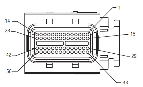
56-Way ζευγάρωμα Connector Προβολή

[/fusion_text][/fusion_builder_column][fusion_builder_column type=”1_3layout=”1_3spacing=”” center_content=nolink=”” target=_selfmin_height=”” hide_on_mobile=small-visibility,medium-visibility,large-visibilityclass=”” id=”” background_color=”” background_image=”” background_image_id=”” background_position=left topbackground_repeat=no-repeathover_type=noneborder_size=”0″ border_color=”” border_style=solidborder_position=allpadding_top=”” padding_right=”” padding_bottom=”” padding_left=”” margin_top=”” margin_bottom=”” animation_type=”” animation_direction=leftanimation_speed=”0.3″ animation_offset=”” last=no”][fusion_imageframe image_id=”14635|fullmax_width=”” style_type=”” blur=”” stylecolor=”” hover_type=nonebordersize=”” bordercolor=”” borderradius=”” align=centerlightbox=nogallery_id=”” lightbox_image=”” lightbox_image_id=”” alt=”Υψηλής τάσης DC Connector Δείτε Yazaki σύνδεσης” link=”” linktarget=_selfhide_on_mobile=small-visibility,medium-visibility,large-visibilityclass=”” id=”” animation_type=”” animation_direction=leftanimation_speed=”0.3″ animation_offset=””]https://www.globaltransmissionsupply.com/wp-content/uploads/High-Voltage-DC-Connector-View.jpg[/fusion_imageframe][fusion_text columns=”” column_min_width=”” column_spacing=”” rule_style=defaultrule_size=”” rule_color=”” hide_on_mobile=small-visibility,medium-visibility,large-visibilityclass=”” id=””]

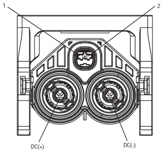
Υψηλής τάσης DC Connector Δείτε Yazaki σύνδεσης
[/fusion_text][/fusion_builder_column][fusion_builder_column type=”1_3layout=”1_3spacing=”” center_content=nolink=”” target=_selfmin_height=”” hide_on_mobile=small-visibility,medium-visibility,large-visibilityclass=”” id=”” background_color=”” background_image=”” background_image_id=”” background_position=left topbackground_repeat=no-repeathover_type=noneborder_size=”0″ border_color=”” border_style=solidborder_position=allpadding_top=”” padding_right=”” padding_bottom=”” padding_left=”” margin_top=”” margin_bottom=”” animation_type=”” animation_direction=leftanimation_speed=”0.3″ animation_offset=”” last=no”][fusion_imageframe image_id=”14213|mediummax_width=”” style_type=”” blur=”” stylecolor=”” hover_type=nonebordersize=”” bordercolor=”” borderradius=”” align=centerlightbox=nogallery_id=”” lightbox_image=”” lightbox_image_id=”” alt=Mating Connector View Deutsch 19 – Τρόπος” link=”” linktarget=_selfhide_on_mobile=small-visibility,medium-visibility,large-visibilityclass=”” id=”” animation_type=”” animation_direction=leftanimation_speed=”0.3″ animation_offset=””]https://www.globaltransmissionsupply.com/wp-content/uploads/Eaton-Fuller-Harness-Connector-View-300×289.jpg[/fusion_imageframe][fusion_text columns=”” column_min_width=”” column_spacing=”” rule_style=defaultrule_size=”” rule_color=”” hide_on_mobile=small-visibility,medium-visibility,large-visibilityclass=”” id=””]

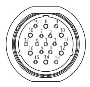
Mating Connector View Deutsch 19 – Τρόπος

[/fusion_text][/fusion_builder_column][/fusion_builder_row][/fusion_builder_container][fusion_builder_container hundred_percent=nohundred_percent_height=nohundred_percent_height_scroll=nohundred_percent_height_center_content=yesequal_height_columns=nomenu_anchor=”” hide_on_mobile=small-visibility,medium-visibility,large-visibilitystatus=publishedpublish_date=”” class=”” id=”” background_color=”” background_image=”” background_position=center centerbackground_repeat=no-repeatfade=nobackground_parallax=noneenable_mobile=noparallax_speed=”0.3″ video_mp4=”” video_webm=”” video_ogv=”” video_url=”” video_aspect_ratio=”16:9″ video_loop=yesvideo_mute=yesvideo_preview_image=”” border_size=”” border_color=”” border_style=solidmargin_top=”” margin_bottom=”” padding_top=”” padding_right=”” padding_bottom=”” padding_left=””][fusion_builder_row][fusion_builder_column type=”1_1layout=”1_1spacing=”” center_content=nolink=”” target=_selfmin_height=”” hide_on_mobile=small-visibility,medium-visibility,large-visibilityclass=”” id=”” background_image_id=”” background_color=”#000000″ background_image=”” background_position=left topundefined=”” background_repeat=no-repeathover_type=noneborder_size=”0″ border_color=”” border_style=solidborder_position=allpadding_top=”” padding_right=”” padding_bottom=”” padding_left=”” margin_top=”” margin_bottom=”” animation_type=”” animation_direction=leftanimation_speed=”0.3″ animation_offset=”” last=no”][fusion_text columns=”” column_min_width=”” column_spacing=”” rule_style=defaultrule_size=”” rule_color=”” hide_on_mobile=small-visibility,medium-visibility,large-visibilityclass=”” id=””]

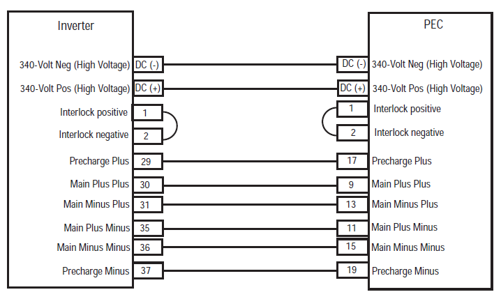
ΣΗΜΕΙΩΣΗ: Αναφέρομαι στο Eaton υβριδικά Component και σύνδεσης Τοποθεσία για Connector Τοποθεσίες σε MY08 Συστήματα
[/fusion_text][/fusion_builder_column][fusion_builder_column type=”1_1layout=”1_1spacing=”” center_content=nolink=”” target=_selfmin_height=”” hide_on_mobile=small-visibility,medium-visibility,large-visibilityclass=”” id=”” background_color=”” background_image=”” background_image_id=”” background_position=left topbackground_repeat=no-repeathover_type=noneborder_size=”0″ border_color=”” border_style=solidborder_position=allpadding_top=”” padding_right=”” padding_bottom=”” padding_left=”” margin_top=”” margin_bottom=”” animation_type=”” animation_direction=leftanimation_speed=”0.3″ animation_offset=”” last=no”][fusion_imageframe image_id=”14666|fullmax_width=”” style_type=”” blur=”” stylecolor=”” hover_type=nonebordersize=”” bordercolor=”” borderradius=”” align=centerlightbox=nogallery_id=”” lightbox_image=”” lightbox_image_id=”” alt=Inverter PEC connectors Eaton Fuller Hybrid transmissionlink=”” linktarget=_selfhide_on_mobile=small-visibility,medium-visibility,large-visibilityclass=”” id=”” animation_type=”” animation_direction=leftanimation_speed=”0.3″ animation_offset=””]https://www.globaltransmissionsupply.com/wp-content/uploads/Inverter-PEC-connectors.png[/fusion_imageframe][/fusion_builder_column][/fusion_builder_row][/fusion_builder_container][fusion_builder_container hundred_percent=nohundred_percent_height=nohundred_percent_height_scroll=nohundred_percent_height_center_content=yesequal_height_columns=nomenu_anchor=”” hide_on_mobile=small-visibility,medium-visibility,large-visibilitystatus=publishedpublish_date=”” class=”” id=”” background_color=”” background_image=”” background_position=center centerbackground_repeat=no-repeatfade=nobackground_parallax=noneenable_mobile=noparallax_speed=”0.3″ video_mp4=”” video_webm=”” video_ogv=”” video_url=”” video_aspect_ratio=”16:9″ video_loop=yesvideo_mute=yesvideo_preview_image=”” border_size=”” border_color=”” border_style=solidmargin_top=”” margin_bottom=”” padding_top=”” padding_right=”” padding_bottom=”” padding_left=””][fusion_builder_row][fusion_builder_column type=”1_1layout=”1_1spacing=”” center_content=nolink=”” target=_selfmin_height=”” hide_on_mobile=small-visibility,medium-visibility,large-visibilityclass=”” id=”” background_color=”” background_image=”” background_image_id=”” background_position=left topbackground_repeat=no-repeathover_type=noneborder_size=”0″ border_color=”” border_style=solidborder_position=allpadding_top=”” padding_right=”” padding_bottom=”” padding_left=”” margin_top=”” margin_bottom=”” animation_type=”” animation_direction=leftanimation_speed=”0.3″ animation_offset=”” last=no”][fusion_modal name=warnings_cautionstitle=”προειδοποιήσεις & Προφυλάξεις” size=largebackground=”” border_color=”” show_footer=yesclass=”” id=””]Κίνδυνος: Κίνδυνος σημαίνει πως θα τραυματιστεί σοβαρά ή σκοτώνονται, αν δεν ακολουθήσει την ενδεδειγμένη διαδικασία.
Προειδοποίηση: Προειδοποίηση υποδεικνύει άμεσο κίνδυνο, η οποία θα μπορούσε να οδηγήσει σε σοβαρό τραυματισμό, αν δεν ακολουθήσετε τη διαδικασία που αναφέρεται.
Προσοχή: Προσοχή υποδεικνύει όχημα ή υλικές ζημιές θα μπορούσε να συμβεί, αν δεν ακολουθήσετε τη διαδικασία που αναφέρεται.

Σημείωση: Σημείωση υποδεικνύει επιπλέον λεπτομέρεια που θα βοηθήσει στη διάγνωση ή την επισκευή ενός συστατικού / σύστημα.

Ακολουθήστε τις διαδικασίες που ορίζονται με την αναφερόμενη σειρά για να αποφύγετε τραυματισμούς:

1. Αν οι κώνοι υψηλής τάσης είναι γύρω από το όχημα και το lockout είναι εγκατεστημένο στον PEC, το μόνο πρόσωπο που θα πρέπει να έχουν τη δυνατότητα να ξεκινήσει το όχημα είναι το πρόσωπο που υπέγραψε την ετικέτα κλειδώματος.
2. Πριν από κάθε εργασία σε ένα όχημα ή εξέρχονται από την καμπίνα, ενώ ο κινητήρας είναι σε λειτουργία, θα πρέπει να τοποθετήσετε τον μοχλό αλλαγής ταχυτήτων στη «Ν» που το χειρόφρενο, και να μπλοκάρει τους τροχούς.
3. Για λόγους ασφαλείας, πάντα εμπλέκονται τα φρένα υπηρεσίας πριν από την επιλογή θέσεις ταχυτήτων από το «Ν»
4. Πριν ξεκινήσετε ένα όχημα πάντα να κάθονται στο κάθισμα του οδηγού, επιλέξτε «Ν», για τον έλεγχο μετατόπισης, και ρυθμίστε τα φρένα στάθμευσης.
5. Σε οχήματα με EPTO, ο κινητήρας / ή και
Motor / γεννήτρια μπορεί να ξεκινήσει σε λειτουργία EPTO. Ποτέ μην εκτελέσει οποιαδήποτε συντήρηση ή εργάζονται σε όχημα, ενώ σε αυτή την κατάσταση.
6. 12-Volt μπαταρίας θετική (+) και αρνητικά (-) πρέπει να αποσυνδεθεί πριν από οποιαδήποτε συγκόλληση σε οποιοδήποτε Hybrid εξοπλισμένο όχημα.

Προσοχή: Ακολουθήστε τις διαδικασίες που ορίζονται με την αναφερόμενη σειρά για να αποφευχθεί η δυσλειτουργία του εξοπλισμού ή τη ζημία.
Προσοχή: Μην αφήστε το χειρόφρενο ή να προσπαθήσει να επιλέξετε ταχύτητα έως ότου η πίεση του αέρα είναι στο σωστό επίπεδο.
Προσοχή: Για να αποφύγετε ζημιά στο κιβώτιο ταχυτήτων κατά τη διάρκεια της ρυμούλκησης θέση του μοχλού αλλαγής ταχυτήτων στο «Ν» και να άρει τους κινητήριους τροχούς από το έδαφος ή αποσυνδέστε το σύστημα μετάδοσης κίνησης.

Προειδοποιήσεις Υψηλής Τάσης & Προφυλάξεις

  • Χρησιμοποιήστε CO2 ή ξηρές χημικές ουσίες πυροσβεστήρες.
  • Η καλωδίωση υψηλής τάσης καλύπτεται με πορτοκαλί χρώμα μόνωση ή μπερδεμένη σωλήνωση και επισημαίνονται με προειδοποιητικές ετικέτες στα συνδετήρες.
  • Όλα τα Eaton® Υβριδικό Diesel Ηλεκτρικά οχήματα / θα φέρει την ένδειξη «Hybrid’ στο εξωτερικό του οχήματος, μαζί με τη σήμανση στροφή στο ταμπλό.
  • Ανατρέξτε στην ΚΑΕ για την συγκεκριμένη θέση του πλαισίου τοποθετούνται υβριδικών εξαρτημάτων.
  • Μην κόβετε στα πορτοκαλί καλώδια υψηλής τάσης.
  • Μην κόβετε σε ή να ανοίξετε την PEC.
  • Μην κόβετε σε ή να ανοίξετε το μετατροπέα DC / DC.
  • Μην κόβετε σε ή να ανοίξετε το μετατροπέα.

Μια ρυθμιστική ζώνη πρέπει να συσταθεί και υψηλής τάσης με μόνωση από καουτσούκ γάντια (τάξη 0 με δερμάτινα προστατευτικά) απαιτούνται προτού εργαστούν με υψηλής τάσης. Εάν δεν ακολουθήσετε αυτές τις οδηγίες μπορεί να οδηγήσει σε σοβαρό τραυματισμό ή θάνατο.
Τα λαστιχένια μόνωση γάντια που πρέπει να φορεθεί, ενώ εργάζονται για το σύστημα υψηλής τάσης είναι κατηγορίας 0 με δερμάτινα προστατευτικά. Τα λαστιχένια γάντια θα πρέπει να ελέγχονται πριν από κάθε χρήση σύμφωνα με τη διαδικασία λαστιχένια μόνωση γάντια δοκιμές που βρέθηκαν στο «διαγνωστικά εργαλεία / Υπηρεσία Εκδόσεων» στη σελίδα 6. Εάν δεν ακολουθήσετε αυτές τις οδηγίες μπορεί να οδηγήσει σε σοβαρό τραυματισμό ή θάνατο.
Πριν από την επιθεώρηση ή εργάζονται σε οποιοδήποτε καλώδια υψηλής τάσης ή συνιστώσες της «υψηλής τάσης Υπηρεσία Shutdown και Power-Up Διαδικασία» στη σελίδα 4 θα πρέπει να ακολουθηθεί. Εάν δεν ακολουθήσετε αυτές τις οδηγίες μπορεί να οδηγήσει σε σοβαρό τραυματισμό ή θάνατο.
Οι συσκευές κλειδώματος και Tagout πρέπει να αφαιρεθεί μόνο από τον τεχνικό που τοποθετείται τις συσκευές κλειδώματος και Tagout στο όχημα. Εάν δεν ακολουθήσετε αυτές τις οδηγίες μπορεί να οδηγήσει σε σοβαρό τραυματισμό ή θάνατο.
Υψηλής τάσεως λαστιχένια μονωτικά γάντια (τάξη 0 με δερμάτινα προστατευτικά) πρέπει να φοριούνται κατά την εργασία σε οποιαδήποτε
καλώδια υψηλής τάσης. Η «Shutdown Υψηλής Τάσης Υπηρεσία και Power-Up Διαδικασία» στη σελίδα 4 πρέπει να ακολουθούνται πριν από την αφαίρεση των τυχόν καλώδια υψηλής τάσης. Εάν δεν ακολουθήσετε αυτές τις οδηγίες μπορεί να οδηγήσει σε σοβαρό τραυματισμό ή θάνατο.
καλώδια υψηλής τάσης και την καλωδίωση είναι πορτοκαλί και περιέχουν μια ετικέτα προειδοποίησης στις υποδοχές. Τα εξαρτήματα υψηλής τάσης σημειώνονται με ετικέτα. Υψηλής τάσεως λαστιχένια μονωτικά γάντια (τάξη 0 με δερμάτινα προστατευτικά) πρέπει να χρησιμοποιείται κατά την εργασία σε οποιοδήποτε από αυτά τα συστατικά. Εάν δεν ακολουθήσετε αυτές τις οδηγίες μπορεί να οδηγήσει σε σοβαρό τραυματισμό ή θάνατο.

Υψηλής Τάσης διαδικασίες τερματισμού των υπηρεσιών

Υψηλής Τάσης Τερματισμός υπηρεσιών και Power-Up Διαδικασία1. Ακολουθήστε «υψηλής τάσης του χώρου εργασίας» διαδικασία.
2. Εντοπίστε το κόκκινο διακόπτη PEC Υπηρεσία στο μπροστινό μέρος της PEC και σπρώξτε απενεργοποιήσετε.
3. Αφαιρέστε το κάλυμμα του διακόπτη υπηρεσία και να εγκαταστήσετε το βραχίονα κλειδώματος (J48506).
4. Στερεώστε ετικέτα με το Lockout Στήριγμα.
5. Βεβαιωθείτε ότι ο διακόπτης PEC Υπηρεσία δεν μπορεί να μετακινηθεί από τη θέση off.
6. Αφήστε το σύστημα να θέσει ένα ελάχιστο 5 λεπτά να εκπληρώσει υψηλής τάσης.
7. Συνδέστε ServiceRanger και δείτε την οθόνη PID Δεδομένων 116 που ονομάζεται «Υψηλής Τάσης Δυναμικό μπαταρίας.» Χρήση SPN 520323 για τη σύνδεση J1939 «Τάση μπαταρίας RB» (ρελέ ασφαλείας).
8. Η τάση πρέπει να είναι 30 volts ή λιγότερο. Αν η τάση είναι πάνω από 30 βολτ, δεν λειτουργούν στο όχημα και να επικοινωνήσετε Eaton® σε 1-800-826-HELP (4357).
9. Γυρίστε το κλειδί ανάφλεξης μακριά και να προχωρήσει στην επισκευή ή βήμα αντιμετώπισης προβλημάτων.
Σημείωση: Η τάση πέφτει στο μηδέν όταν το κλειδί είναι εκτός λειτουργίας.

Υψηλής Τάσης Υπηρεσία Power-Up Διαδικασία

1. Εγκαταστήστε όλα τα βύσματα σύνδεσης υψηλής τάσης στην κλειδωμένη θέση τους.
2. Εάν είστε το πρόσωπο που εργάζεται επί του οχήματος, αφαιρέστε το Lockout βραχίονα και ετικέτα.
3. Τοποθετήστε ξανά το Lockout βραχίονα πάνω από το διακόπτη Υπηρεσία.
4. Τραβήξτε την Υπηρεσία Αλλαγή έξω και αφήστε το σύνολο του οχήματος για 2 λεπτά.
5. Start vehicle when appropriate.[/fusion_modal][fusion_modal name=component_locationtitle=”Eaton υβριδικά Component και σύνδεσης Τοποθεσία ” size=largebackground=”#ffffffborder_color=”” show_footer=yesclass=”” id=””]

Eaton υβριδικά Component και Τοποθεσίες σύνδεσης MY08 Συστήματα

[/fusion_modal][fusion_modal name=component_location2title=”Eaton υβριδικά Component και σύνδεσης Τοποθεσία MY09 Συστήματα” size=largebackground=”#ffffffborder_color=”” show_footer=yesclass=”” id=””]

Eaton υβριδικά Component και Τοποθεσίες σύνδεσης MY09 Συστήματα

[/fusion_modal][/fusion_builder_column][/fusion_builder_row][/fusion_builder_container][fusion_builder_container hundred_percent=nohundred_percent_height=nohundred_percent_height_scroll=nohundred_percent_height_center_content=yesequal_height_columns=nomenu_anchor=”” hide_on_mobile=small-visibility,medium-visibility,large-visibilitystatus=publishedpublish_date=”” class=”” id=”” background_color=”” background_image=”” background_position=center centerbackground_repeat=no-repeatfade=nobackground_parallax=noneenable_mobile=noparallax_speed=”0.3″ video_mp4=”” video_webm=”” video_ogv=”” video_url=”” video_aspect_ratio=”16:9″ video_loop=yesvideo_mute=yesvideo_preview_image=”” border_size=”” border_color=”” border_style=solidmargin_top=”” margin_bottom=”” padding_top=”” padding_right=”” padding_bottom=”” padding_left=””][fusion_builder_row][fusion_builder_column type=”1_1layout=”1_1spacing=”” center_content=nolink=”” target=_selfmin_height=”” hide_on_mobile=small-visibility,medium-visibility,large-visibilityclass=”” id=”” background_color=”” background_image=”” background_image_id=”” background_position=left topbackground_repeat=no-repeathover_type=noneborder_size=”0″ border_color=”” border_style=solidborder_position=allpadding_top=”” padding_right=”” padding_bottom=”” padding_left=”” margin_top=”” margin_bottom=”” animation_type=”” animation_direction=leftanimation_speed=”0.3″ animation_offset=”” last=no”][fusion_content_boxes layout=clean-horizontalcolumns=”2″ title_size=”18pxheading_size=”3″ title_color=”#ffffffbody_color=”#ffffffbackgroundcolor=”#4f4f4ficon=”” iconflip=”” iconrotate=”” iconspin=noiconcolor=”” icon_circle=”” icon_circle_radius=”” circlecolor=”” circlebordersize=”” circlebordercolor=”” outercirclebordersize=”” outercirclebordercolor=”” icon_size=”” icon_hover_type=”” hover_accent_color=”” image=”” image_id=”” image_width=”” image_height=”” link_type=”” button_span=”” link_area=”” link_target=”” icon_align=leftanimation_type=”” animation_delay=”” animation_offset=”” animation_direction=leftanimation_speed=”0.3″ margin_top=”” margin_bottom=”” hide_on_mobile=small-visibility,medium-visibility,large-visibilityclass=”” id=””][fusion_content_box title=ΒΗΜΑ 1. Επαλήθευση FMIS παρούσα.backgroundcolor=”” icon=”” iconflip=”” iconrotate=”” iconspin=noiconcolor=”” circlecolor=”” circlebordersize=”” circlebordercolor=”” outercirclebordersize=”” outercirclebordercolor=”” image=”” image_id=”” image_width=”” image_height=”” link=”” linktext=”Διαβάστε περισσότερα” link_target=”” animation_type=”” animation_direction=leftanimation_speed=”0.3″ animation_offset=””]

  1. Διαβάστε και ακολουθήστε το προειδοποιήσεις & Προφυλάξεις.
  2. Ανάκτηση Active κωδικών βλάβης και FMIS με ServiceRanger χρησιμοποιώντας το 9-Way διαγνωστικός συνδετήρας.
    Κίνδυνος: Βλέπω Υψηλής Τάσης Τερματισμός υπηρεσιών και Power-Up Διαδικασίες. Ακολουθήστε τις διαδικασίες για την αποφυγή κραδασμών, καίγονται ή θανάτου από κακώς αντιμετωπίζονται υψηλής τάσης.
  3. Ποια FMIS υπάρχουν
    • Αν σφάλμα κώδικα 116 ΔΝΤ 14 είναι εισηγμένη, μεταβείτε στο Βήμα 9.
    • Αν σφάλμα κώδικα 116 ΔΝΤ 10 είναι εισηγμένη, μεταβείτε στο Βήμα 2.
    • If no Fault Codes are listed, The Service Switch was pushed in. Πηγαίνετε στο βήμα 10.

[/fusion_content_box][fusion_content_box title=ΒΗΜΑ 2. Verify Data Monitor parameters.backgroundcolor=”” icon=”” iconflip=”” iconrotate=”” iconspin=noiconcolor=”” circlecolor=”” circlebordersize=”” circlebordercolor=”” outercirclebordersize=”” outercirclebordercolor=”” image=”” image_id=”” image_width=”” image_height=”” link=”” linktext=”Διαβάστε περισσότερα” link_target=”” animation_type=”” animation_direction=leftanimation_speed=”0.3″ animation_offset=””]

  1. Κλειδί για την.
  2. Συνδέστε ServiceRanger στο 9-Way διαγνωστικός συνδετήρας στην καμπίνα.
  3. Επιλέξτε την επιλογή «Monitor Data».
  4. View the Battery Pack Voltage (BCU1) PID 118 in the high- voltage Battery list:
    • If the Battery Pack Voltage (BCU1) PID 118 is greater than 200 βολτ, μεταβείτε στο Βήμα 3.
    • If the Battery Pack Voltage (BCU1) PID 118 είναι λιγότερο από 200 βολτ, αντικαταστήστε το Carrier Ηλεκτρονικών Ισχύος (PEC), Στη συνέχεια μεταβείτε στο Βήμα 10.

[/fusion_content_box][/fusion_content_boxes][fusion_content_boxes layout=clean-horizontalcolumns=”2″ title_size=”18pxheading_size=”3″ title_color=”#ffffffbody_color=”#ffffffbackgroundcolor=”#4f4f4ficon=”” iconflip=”” iconrotate=”” iconspin=noiconcolor=”” icon_circle=”” icon_circle_radius=”” circlecolor=”” circlebordersize=”” circlebordercolor=”” outercirclebordersize=”” outercirclebordercolor=”” icon_size=”” icon_hover_type=”” hover_accent_color=”” image=”” image_id=”” image_width=”” image_height=”” link_type=”” button_span=”” link_area=”” link_target=”” icon_align=leftanimation_type=”” animation_delay=”” animation_offset=”” animation_direction=leftanimation_speed=”0.3″ margin_top=”” margin_bottom=”” hide_on_mobile=small-visibility,medium-visibility,large-visibilityclass=”” id=””][fusion_content_box title=ΒΗΜΑ 3. Verify continuity of Inverter connector circuits.backgroundcolor=”” icon=”” iconflip=”” iconrotate=”” iconspin=noiconcolor=”” circlecolor=”” circlebordersize=”” circlebordercolor=”” outercirclebordersize=”” outercirclebordercolor=”” image=”” image_id=”” image_width=”” image_height=”” link=”” linktext=”Διαβάστε περισσότερα” link_target=”” animation_type=”” animation_direction=leftanimation_speed=”0.3″ animation_offset=””]

  1. Βασικά off.
  2. If the vehicle is not equipped with a DC/DC Converter or APG, skip this step.
  3. Using ASTM Class 0 electrical insulating rubber gloves with leather protectors, disconnect the DC cable for the DC/DC Converter and APG at the PEC.
  4. With the key off, temporarily remove the Lockout Bracket and pull the Service Switch out.
  5. Κλειδί για την.
  6. Είναι σφάλμα κώδικα 116 ΔΝΤ 10 still Active in ServiceRanger?
    • Αν σφάλμα κώδικα 116 ΔΝΤ 10 is Active with the DC/DC Converter and APG disconnected, μεταβείτε στο Βήμα 4.
    • Αν σφάλμα κώδικα 116 ΔΝΤ 10 is no longer Active with the DC/DC Converter and APG disconnected, key off and reinstall the Lockout Bracket on the PEC. Replace the Power Electronics Carrier (PEC), Στη συνέχεια μεταβείτε στο Βήμα 10.

[/fusion_content_box][fusion_content_box title=ΒΗΜΑ 4. Verify continuity of PEC connector circuits to ground.backgroundcolor=”” icon=”” iconflip=”” iconrotate=”” iconspin=”” iconcolor=”” circlecolor=”” circlebordersize=”” circlebordercolor=”” outercirclebordersize=”” outercirclebordercolor=”” image=”” image_id=”” image_width=”” image_height=”” link=”” linktext=”” link_target=”” animation_type=”” animation_direction=leftanimation_speed=”0.3″ animation_offset=””]

  1. Βασικά off.
  2. Αποσυνδέστε το PEC 19-Way σύνδεσης.
  3. Temporarily remove the Lockout Bracket and pull the Service Switch out.
    Σημείωση: Ensure the Key Switch is off.
  4. Measure resistance at the PEC 19-Way Connector Terminal at the following pins:
    • Καρφίτσα 17 με Pin 19
    • Καρφίτσα 9 με Pin 11
    • Καρφίτσα 13 με Pin 15
      • If the resistance between Pins 17 και Pin 19 είναι 112-122 ohms και η αντίσταση από Pin 9 με Pin 11 και Pin 13 με Pin 15 είναι το καθένα 33-37 Ω, μεταβείτε στο Βήμα 5.
      • Εάν η αντίσταση είναι εκτός εύρους, μεταβείτε στο Βήμα 6.

[/fusion_content_box][/fusion_content_boxes][fusion_content_boxes layout=clean-horizontalcolumns=”2″ title_size=”18pxheading_size=”3″ title_color=”#ffffffbody_color=”#ffffffbackgroundcolor=”#4f4f4ficon=”” iconflip=”” iconrotate=”” iconspin=noiconcolor=”” icon_circle=”” icon_circle_radius=”” circlecolor=”” circlebordersize=”” circlebordercolor=”” outercirclebordersize=”” outercirclebordercolor=”” icon_size=”” icon_hover_type=”” hover_accent_color=”” image=”” image_id=”” image_width=”” image_height=”” link_type=”” button_span=”” link_area=”” link_target=”” icon_align=leftanimation_type=”” animation_delay=”” animation_offset=”” animation_direction=leftanimation_speed=”0.3″ margin_top=”” margin_bottom=”” hide_on_mobile=small-visibility,medium-visibility,large-visibilityclass=”” id=””][fusion_content_box title=ΒΗΜΑ 5. Verify continuity of Inverter connector circuits to ground.backgroundcolor=”” icon=”” iconflip=”” iconrotate=”” iconspin=noiconcolor=”” circlecolor=”” circlebordersize=”” circlebordercolor=”” outercirclebordersize=”” outercirclebordercolor=”” image=”” image_id=”” image_width=”” image_height=”” link=”” linktext=”Διαβάστε περισσότερα” link_target=”” animation_type=”” animation_direction=leftanimation_speed=”0.3″ animation_offset=””]

  1. Βασικά off.
  2. Reconnect the PEC 19-Way Connector.
  3. Αποσυνδέστε το μετατροπέα 56-Way σύνδεσης.
  4. Inspect the connector pins for damaged, corroded and/or loose wires.
  5. Measure resistance between the Inverter 56-Way Connector at the following pins:
    • Καρφίτσα 29 με Pin 37
    • Καρφίτσα 30 με Pin 35
    • Καρφίτσα 31 με Pin 36 Σημείωση: flex απαλά το μετατροπέα 56-Way φις της καλωδίωσης κοντά στην υποδοχή, ενώ παρακολουθεί τις τιμές αντίστασης.
      • Εάν η αντίσταση μεταξύ Pin 29 και Pin 37 είναι 112-122 ohms και η αντίσταση από Pin 30 με Pin 35 και Pin 31 με Pin 36 είναι το καθένα 33-37 Ω, push the Service Switch on the PEC and reinstall the Lockout Bracket. Πηγαίνετε στο βήμα 8.
      • Εάν η αντίσταση είναι εκτός εύρους, repair the Hybrid Harness between the PEC and Inverter, Στη συνέχεια μεταβείτε στο Βήμα 10.

[/fusion_content_box][fusion_content_box title=ΒΗΜΑ 6. Verify continuity of PEC connector circuits.backgroundcolor=”” icon=”” iconflip=”” iconrotate=”” iconspin=”” iconcolor=”” circlecolor=”” circlebordersize=”” circlebordercolor=”” outercirclebordersize=”” outercirclebordercolor=”” image=”” image_id=”” image_width=”” image_height=”” link=”” linktext=”” link_target=”” animation_type=”” animation_direction=leftanimation_speed=”0.3″ animation_offset=””]

  1. Βασικά off.
  2. Remove the Air Filter Cover and Air Filter from the PEC. Refer to TRSM1000 for procedures.*
  3. An Inertia Switch is located at the front of the PEC inside the box and viewable when the Air Filter is removed.
  4. Using ASTM Class 0 electrical insulating rubber gloves with leather protectors, press the button on the top of the Inertia Switch until heard or felt a click. This switch must be depressed a set distance to reset the switch.
  5. Measure resistance at the PEC 19-Way Connector Terminal at the following pins:
    • Καρφίτσα 17 με Pin 19
    • Καρφίτσα 9 με Pin 11
    • Καρφίτσα 13 με Pin 15
      • qIf the resistance between Pin 17 και Pin 19 είναι 112-122 ohms και η αντίσταση από Pin 9 με Pin 11 και Pin 13 με Pin 15 είναι το καθένα 33-37 Ω, the Inertia Switch was tripped. Test is complete. Πηγαίνετε στο βήμα 10.
      • Εάν η αντίσταση είναι εκτός εύρους, push in the Service Switch on the PEC and reinstall the Lockout Bracket, Στη συνέχεια μεταβείτε στο Βήμα 7.

[/fusion_content_box][/fusion_content_boxes][fusion_content_boxes layout=clean-horizontalcolumns=”2″ title_size=”18pxheading_size=”3″ title_color=”#ffffffbody_color=”#ffffffbackgroundcolor=”#4f4f4ficon=”” iconflip=”” iconrotate=”” iconspin=noiconcolor=”” icon_circle=”” icon_circle_radius=”” circlecolor=”” circlebordersize=”” circlebordercolor=”” outercirclebordersize=”” outercirclebordercolor=”” icon_size=”” icon_hover_type=”” hover_accent_color=”” image=”” image_id=”” image_width=”” image_height=”” link_type=”” button_span=”” link_area=”” link_target=”” icon_align=leftanimation_type=”” animation_delay=”” animation_offset=”” animation_direction=leftanimation_speed=”0.3″ margin_top=”” margin_bottom=”” hide_on_mobile=small-visibility,medium-visibility,large-visibilityclass=”” id=””][fusion_content_box title=ΒΗΜΑ 7. Verify continuity of Inverter connector circuits.backgroundcolor=”” icon=”” iconflip=”” iconrotate=”” iconspin=noiconcolor=”” circlecolor=”” circlebordersize=”” circlebordercolor=”” outercirclebordersize=”” outercirclebordercolor=”” image=”” image_id=”” image_width=”” image_height=”” link=”” linktext=”Διαβάστε περισσότερα” link_target=”” animation_type=”” animation_direction=leftanimation_speed=”0.3″ animation_offset=””]

  1. Βασικά off.
  2. Disconnect the DC High-Voltage Cable at the PEC Bulkhead and at the Inverter Bulkhead.
  3. Measure resistance between the Low-Voltage Interlock Pins on the PEC side of the DC High-Voltage Cable:
    Σημείωση: The Interlock Pins are the two small spade terminals located in the same opening.

    • If the resistance is 0–0.3 ohms between the Interlock Loop Pins, αντικαταστήστε το Carrier Ηλεκτρονικών Ισχύος (PEC), Στη συνέχεια μεταβείτε στο Βήμα 10.
    • Εάν η αντίσταση είναι εκτός εύρους, αντικαταστήστε το καλώδιο υψηλής τάσης DC, Στη συνέχεια μεταβείτε στο Βήμα 10.

[/fusion_content_box][fusion_content_box title=ΒΗΜΑ 8. Verify continuity of DC Cable from PEC to Inverter Connector circuits.backgroundcolor=”” icon=”” iconflip=”” iconrotate=”” iconspin=”” iconcolor=”” circlecolor=”” circlebordersize=”” circlebordercolor=”” outercirclebordersize=”” outercirclebordercolor=”” image=”” image_id=”” image_width=”” image_height=”” link=”” linktext=”” link_target=”” animation_type=”” animation_direction=leftanimation_speed=”0.3″ animation_offset=””]

  1. Βασικά off.
  2. Disconnect the DC High-Voltage Cable at the PEC Bulkhead and the Inverter Bulkhead.
  3. Measure the resistance of each high-voltage circuit on the cable:
    • If the resistance of each high-voltage circuit in the cable is 1 Ω ή λιγότερο, αντικαταστήστε το μετατροπέα, Στη συνέχεια μεταβείτε στο Βήμα 10.
    • Εάν η αντίσταση είναι εκτός εύρους, replace the DC High-Voltage Cable, Στη συνέχεια μεταβείτε στο Βήμα 10.

[/fusion_content_box][/fusion_content_boxes][fusion_content_boxes layout=clean-horizontalcolumns=”2″ title_size=”18pxheading_size=”3″ title_color=”#ffffffbody_color=”#ffffffbackgroundcolor=”#4f4f4ficon=”” iconflip=”” iconrotate=”” iconspin=noiconcolor=”” icon_circle=”” icon_circle_radius=”” circlecolor=”” circlebordersize=”” circlebordercolor=”” outercirclebordersize=”” outercirclebordercolor=”” icon_size=”” icon_hover_type=”” hover_accent_color=”#f41000image=”” image_id=”” image_width=”” image_height=”” link_type=”” button_span=”” link_area=”” link_target=”” icon_align=leftanimation_type=”” animation_delay=”” animation_offset=”” animation_direction=leftanimation_speed=”0.3″ margin_top=”” margin_bottom=”” hide_on_mobile=small-visibility,medium-visibility,large-visibilityclass=”” id=””][fusion_content_box title=ΒΗΜΑ 9. Verify Data Monitor parameters.backgroundcolor=”” icon=”” iconflip=”” iconrotate=”” iconspin=”” iconcolor=”” circlecolor=”” circlebordersize=”” circlebordercolor=”” outercirclebordersize=”” outercirclebordercolor=”” image=”” image_id=”” image_width=”” image_height=”” link=”” linktext=”” link_target=”” animation_type=”” animation_direction=leftanimation_speed=”0.3″ animation_offset=””]

  1. Συνδέστε ServiceRanger στο 9-Way διαγνωστικός συνδετήρας στην καμπίνα.
  2. Επιλέξτε την επιλογή «Monitor Data».
  3. View the following parameters in the High-Voltage Battery list.
    • Battery Pack Voltage (BCU1) PID 118
    • Battery Voltage PID 116
      • If the voltage readings on PID 116 και PID 118 are within 10 βολτ κάθε άλλο, αντικαταστήστε το Carrier Ηλεκτρονικών Ισχύος (PEC), Στη συνέχεια μεταβείτε στο Βήμα 10.
      • If the voltage readings on PID 116 και PID 118 are greater than 10 βολτ κάθε άλλο, αντικαταστήστε το μετατροπέα, Στη συνέχεια μεταβείτε στο Βήμα 10.

[/fusion_content_box][fusion_content_box title=ΒΗΜΑ 10. Επιβεβαιώστε την επισκευή.backgroundcolor=”” icon=”” iconflip=”” iconrotate=”” iconspin=noiconcolor=”” circlecolor=”” circlebordersize=”” circlebordercolor=”” outercirclebordersize=”” outercirclebordercolor=”” image=”” image_id=”” image_width=”” image_height=”” link=”” linktext=”Διαβάστε περισσότερα” link_target=”” animation_type=”” animation_direction=leftanimation_speed=”0.3″ animation_offset=””]

  1. Βασικά off.
  2. Επανασυνδέστε όλες τις συνδέσεις και το αρνητικό καλώδιο της μπαταρίας.
  3. Κλειδί για την.
  4. Σαφείς κώδικες, βλέπω Clear Ανενεργό Βλάβες.
  5. Οδηγήστε το όχημα και να προσπαθήσετε να επαναφέρετε τον κωδικό.
  6. Έλεγχος για κωδικούς, βλέπω Δείτε Ενεργό και Ανενεργό Βλάβες.
    • Αν δεν κωδικοί, δοκιμή είναι πλήρης.
    • Αν σφάλμα κώδικα 116 εμφανίζεται, επικοινωνήστε με τον Eaton στο 1- 800-826-ΒΟΗΘΕΙΑ (4357). Repeat this Step (Βήμα 10).
    • Εάν ένας κωδικός, εκτός από 116 εμφανίζεται, βλέπω Σφάλμα Λίστα Κώδικα Δείκτης.

[/fusion_content_box][/fusion_content_boxes][/fusion_builder_column][/fusion_builder_row][/fusion_builder_container][fusion_global id=”13788″]