Eaton Fuller Гібрыд Трансмісія Код памылкі 73 – Не атрымалася Прыцягнуць Шасцярня
Код памылкі для Eaton гібрыдных мадэляў сістэмы прывадаў (MY08) EH-8E306A-U, EH-8E306A-UPG, EH-8E306A-UP, EH-8E306A-CD, EH-8E306A-T, EH-6E606B-CD, (MY09) EH-8E406A-У / Р, EH-8E406A-UP, EH-8E406A-UPG, EH-8E406A-CD, EH-8E406A-CDG, EH-8E406A-CDR, EH-8E406A-Т, EH-6E706B-CD, EH-6E706B-Р і EH-6E706B-УПГ. Чытайце ніжэй, каб даведацца, як праверыць, ачысціць і выправіць памылкі коды няспраўнасці для Freightliner, Mack, Peterbilt, Kenworth, Volvo, міжнародны, і цяжкія грузавікі і абсталяванне. Скрынка перадач Электронны блок кіравання кантралюе электрычныя Shifter, які ўваходзіць у зачапленне розныя рэйкі і пазіцыі перадач. Электрычны Shifter складаецца з двух электрарухавікоў, цягавы рухавік і Маторныя. Рухавік Чыгуначны змяняе становішча рэйкі і матор-рэдуктар змяняе становішча перадачы.
код памылкі 73 – Не атрымалася Engage выяўлення перадач
Наступныя папярэднія ўмовы павінны быць выкананы да таго, як сістэма выявіць памылку:
- TECU напружання запальвання вышэй 7 вольт і менш 16 вольт.
- TECU Сістэма батарэі Нізкае напружанне Збой Неактыўны.
- TECU System Battery Voltage Weak Fault is Inactive.
Нататка: Пры ліквідацыі неактыўнага кода звярніцеся да Дыягнастычны рэжым прадукту (ДПМ)
Умовы Усталяваць Код памылкі Актыўны
- МВФ 7 усталёўваецца, калі электрычны Shifter трывае няўдачу 5 паслядоўныя спробы ўдзельнічаць у канкрэтнай пазіцыі шасцярні.
Запасны Калі код няспраўнасці 73 усталяваны наступныя ўмовы:
- Памылка захоўваецца ў памяці TECU.
- Калі мноства няспраўнасцяў падчас кіравання, транспартны сродак захоўвае бягучае становішча.
Умовы паказаны код няспраўнасці Inactive
Толькі Неактыўныя няспраўнасці могуць быць ачышчаны ад блока перадачы электроннага кіравання (TECU) або гісторыя HCM з выкарыстаннем ServiceRanger. TECU аўтаматычна выдаляе інфармацыю аб няспраўнасці з гісторыі пасля таго, як 200 гадзіны і HCM аўтаматычна выдаляе інфармацыю аб няспраўнасці з гісторыі пасля збою былі неактыўнымі 200 гадзін.
Гэты код няспраўнасці можа быць выкліканы любым з наступных:
- МВФ 7
- перацягвання счаплення
- ECA
- Зрух Бар Корпус
- электрычны Shifter
- Снасці Выбар датчыка
- ярмо, слізгальныя муфты, галоўны вал
- TECU
код памылкі 73 – Не атрымалася Engage тэсту шасцярэнькі
ідэнтыфікацыя кампанентаў:
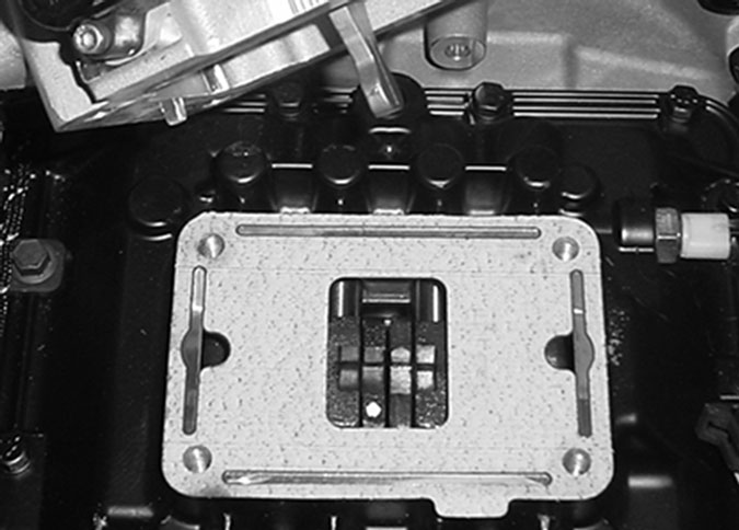
Відэльцаў пераключэння ў нейтральнае становішча.
НАТАТКА: звярніцеся да Eaton Гібрыдныя кампаненты і раздым Размяшчэнне месцазнаходжаньня канектараў ў MY08 сістэмах
НАТАТКА: звярніцеся да Eaton Гібрыдныя кампаненты і раздым Размяшчэнне месцазнаходжаньня канектараў ў MY09 сістэмах.
папярэджання &узмацняльнік; засцярогі
небяспека: Небяспека азначае, што вы будзеце цяжка паранены альбо забіты, калі не будзеце прытрымлівацца ўказанай працэдуры.
папярэджанне: Папярэджанне паказвае на непасрэдную небяспеку, што можа прывесці да цяжкіх цялесных пашкоджанняў, калі вы не будзеце выконваць паказаную працэдуру.
засцярога: Асцярожнасць указвае на пашкоджанне транспартнага сродку або маёмасці, калі вы не будзеце выконваць указаную працэдуру.
Нататка: Заўвага паказвае дадатковую дэталь, якая дапаможа ў дыягностыцы альбо рамонце кампанента / сістэмы.
Выканаеце паказаныя працэдуры ў паказаным парадку, каб пазбегнуць траўмаў:
1. Калі конусы высокага напружання вакол аўтамабіля і блакаванне усталёўваецца на выбарчым участку, адзіны чалавек, які павінен мець магчымасць запуску аўтамабіля з'яўляецца асобай, якія падпісалі блакавальных тэг.
2. Перад пачаткам працы на транспартным сродку ці выхаду з кабіны ў той час як рухавік працуе, Вы павінны змясціць рычаг пераключэння перадач у «N» усталяваны стаяначны тормаз, і блакаваць колы.
3. Па меркаваннях бяспекі, заўсёды задзейнічаць нажной тормаз да выбару пазіцыі перадач ад «N.»
4. Перад тым як пачаць транспартны сродак заўсёды сядзіць на сядзенне кіроўцы, выберыце «N» на кантролі зруху, і ўсталяваць стояночные тормазы.
5. У аўтамабілях з ePTO, рухавік і / або
Рухавік / генератар можа пачацца ў рэжыме ePTO. Ніколі не выконвайце тэхнічнае абслугоўванне або працаваць на транспартным сродку, у той час як у гэтым рэжыме.
6. 12-Volt батарэі станоўчы (+) і адмоўныя (-) павінны быць адключаныя да любой зваркі на любым Гібрыдная абсталяваным аўтамабілі.
засцярога: Выканаеце паказаныя працэдуры ў паказаным парадку, каб пазбегнуць няспраўнасцяў або пашкоджання абсталявання.
засцярога: Не адпускайце стаяначны тормаз і не спрабуйце выбраць перадачу, пакуль ціск паветра не будзе на патрэбным узроўні.
засцярога: Каб пазбегнуць пашкоджання трансмісіі падчас буксіроўкі, пастаўце рычаг пераключэння перадач у становішча "N" і падніміце вядучыя колы ад зямлі альбо адлучыце прывад.
Папярэджання высокага напружання & засцярогі
- Выкарыстанне CO2 ці сухіх хімічных вогнетушыцеляў.
- Драты высокага напружання пакрываюцца ў аранжавых ізаляцыі або згорнутых насосна-кампрэсарных трубах і адзначаны папераджальнымі надпісы на раздымах.
- Усе Eaton® Гібрыдныя Дызельныя / Электрычныя аўтамабілі будуць пазначаныя як «Hybrid’ на вонкавым боку транспартнага сродку, нароўні з цэтлікам зруху на прыборнай панэлі.
- Звярніцеся да OEM для канкрэтнага месцазнаходжаньня шасі ўстаноўлена гібрыдных кампанентаў.
- Ня рэжце ў аранжавыя кабелі высокага напружання.
- НЕ нарэзаць або адкрыць PEC.
- НЕ нарэзаць або адкрыць пераўтваральнік DC / DC.
- НЕ нарэзаць або адкрыць інвертар.
Буферная зона павінна быць ўстаноўлена і высокае напружанне ізаляваны гумовымі пальчаткі (клас 0 скураныя пратэктары) патрабуецца да пачатку працы з высокай напругай. Невыкананне гэтых інструкцый можа прывесці да сур'ёзных траўмам або смерці.
Гумовыя цеплаахоўныя пальчаткі, якія павінны насіць падчас працы ў сістэме высокага напружання ставяцца да класа 0 скураныя пратэктары. Гумовыя пальчаткі павінны быць правераны перад кожным выкарыстаннем, вынікаючы працэдуры гумавай ізаляцыі пальчаткі выпрабаванні знайшлі ў «Сродкі дыягностыкі / Сэрвіс Публікацыі» на старонцы 6. Невыкананне гэтых інструкцый можа прывесці да сур'ёзных траўмам або смерці.
Перад аглядам або працаваць на любых кабеляў або высакавольтных кампанентаў на «High-Voltage Shutdown Service і Power-Up Працэдура» на старонцы 4 павінны выконвацца. Невыкананне гэтых інструкцый можа прывесці да сур'ёзных траўмам або смерці.
Прылады блакіроўкі і Tagout павінны быць выдаленыя толькі з дапамогай тэхнік, якія размешчаны прылады блакіроўкі і Tagout на транспартным сродку. Невыкананне гэтых інструкцый можа прывесці да сур'ёзных траўмам або смерці.
Высакавольтныя гумовай ізаляцыяй пальчаткі (клас 0 скураныя пратэктары) варта насіць пры працы на любым
Кабелі высокага напружання. «Высакавольтны служба Shutdown і Power-Up Працэдура» на старонцы 4 павінен выконвацца перад выдаленнем любых кабеляў высокага напружання. Невыкананне гэтых інструкцый можа прывесці да сур'ёзных траўмам або смерці.
Кабелі высокага напружання і провад аранжавыя колеры і ўтрымліваюць папераджальны ярлык на раздымах. кампаненты высокага напружання пазначаныя цэтлікам. Высакавольтныя гумовай ізаляцыяй пальчаткі (клас 0 скураныя пратэктары) павінны быць выкарыстаны пры працы на любым з гэтых кампанентаў. Невыкананне гэтых інструкцый можа прывесці да сур'ёзных траўмам або смерці.
Высакавольтныя працэдуры Service Shutdown
 1. Выконвайце «Высакавольтны Працоўная зона» Працэдура.
2. Знайдзіце чырвоны PEC Service Switch на пярэдняй панэлі Пэк і націснуць выключыць.
3. Зніміце вечка Service Switch і ўсталяваць кранштэйн Lockout (J48506).
4. Замацаваць тэг лакаўту кранштэйна.
5. Пераканайцеся, што перамыкач PEC службы не можа перайсці ад выключаны палажэнні.
6. Дайце сістэме ўсталяваць як мінімум 5 хвілін разраду высокага напружання.
7. Падключэнне ServiceRanger і прагляду манітора дадзеных PID 116 пад назвай «High-Voltage патэнцыял батарэі.» Выкарыстанне SPN 520323 для падлучэння J1939 «Напруга батарэі RB» (скрынка рэле).
8. Напружанне павінна быць 30 вольт або менш. Калі напружанне вышэй 30 вольт, не працуюць на транспартным сродку і звязацца Eaton® на 1-800-826-HELP (4357).
9. Павярніце ключ запальвання выключана і прыступіць да рамонту або ліквідацыю непаладак,.
Нататка: Напружанне падае да нуля, калі ключ выключаны.
Высакавольтная служба ўключэнне харчаванне Працэдура
1. Усталюйце ўсе раздымы высокага напружання ў заблакаваным стане.
2. Калі вы чалавек, які працуе на транспартным сродку, выдаліць Lockout кранштэйн і тэг.
3. Усталюйце Lockout кранштэйн праз сэрвісны перамыкач.
4. Выцягнеце Service Switch і дайце набор транспартных сродкаў для 2 хвілін.
5. Запусціць аўтамабіль у выпадку неабходнасці.
Eaton Гібрыдныя кампаненты і раздым Размяшчэнне

Eaton Гібрыдныя кампаненты і раздым Размяшчэнне MY09 сістэма

КРОК 1. Праверце зубчасты дысплей ў нейтральным становішчы шасцярні.
- Атрымлівайце актыўныя коды памылак і FMI з дапамогай ServiceRanger з дапамогай 9-кантактнага дыягнастычнага раздыма або ўручную.
- ключ на.
- Месца пераключэння прылады ў нейтральнае становішча.
- Прэс-служба Brake.
- выберыце дыск.
- Назірайце механізм дысплея:
- If there is an Active Fault Code 73, перайдзіце да кроку 2.
- Калі перадача дысплей паказвае цвёрдыя перадачы, перайдзіце да кроку 4.
КРОК 2. Выкананне электраабсталявання Претест.
- Выканайце Электрычная Претест:
- Калі ніякіх праблем не выяўлена ў Электрычнай Претест, перайдзіце да кроку 3.
- Калі праблема была адноўлена ць Электрычнай Претест, перайдзіце да кроку 1.
КРОК 3. Праверка цэласнасці кампанентаў Зрух Бар для дома.
- ключ ад.
- Выдаліць Электрычны Shifter * ад Shift, Бар жыллёва.
- праверце наступнае:
- Зрух блокаў мацуюцца да пераключалых штоков надзейна
- Электрычны Shifter вольны ад любога празмернага забруджвання змазачных нарошчвання
- Два зубчастых пазіцыі не могуць быць задзейнічаны адначасова
- Калі ніякіх праблем не выяўлена, замяніць электрычны Shifter, затым перайдзіце да кроку 4.
- Калі праблема знойдзена, рамонт у адпаведнасці з патрабаваннямі, затым перайдзіце да кроку 4.
КРОК 4. праверка рамонту.
- ключ ад.
- Падлучыце ўсе раздымы і адмоўны кабель акумулятара.
- ключ на.
- ачысціць коды, убачыць Ачысціць Неактыўныя Адмовы.
- Вадзіць аўтамабіль і паспрабаваць скінуць код.
- Праверце коды, убачыць Актыўныя і неактыўныя разломы.
- Калі няма кодаў, тэст завершаны.
- Калі код няспраўнасці 73 з'яўляецца, знайсці памылку ў тэставанні, перайдзіце да кроку 1.
- Калі код, выдатны ад 73 з'яўляецца, убачыць Няспраўнасць Спіс індэксаў код.
любой частка перадачы вам трэба ёсць яго! У той жа дзень перавозка грузу, сусветнай.
ПАТРЭБНА БЯСПЛАТНА ПАДТРЫМКУ АД АДНАГО З НАШЫХ СПЕЦЫЯЛІСТАЎ?