[fusion_builder_container hundred_percent=nohundred_percent_height=nohundred_percent_height_scroll=nohundred_percent_height_center_content=yesequal_height_columns=nomenu_anchor=”” hide_on_mobile=small-visibility,medium-visibility,large-visibilitystatus=publishedpublish_date=”” class=”” id=”” background_color=”” background_image=”” background_position=center centerbackground_repeat=no-repeatfade=nobackground_parallax=noneenable_mobile=noparallax_speed=”0.3″ video_mp4=”” video_webm=”” video_ogv=”” video_url=”” video_aspect_ratio=”16:9″ video_loop=yesvideo_mute=yesvideo_preview_image=”” border_size=”” border_color=”” border_style=solidmargin_top=”35″ margin_bottom=”” padding_top=”” padding_right=”” padding_bottom=”” padding_left=””][fusion_builder_row][fusion_builder_column type=”1_1layout=”1_1spacing=”” center_content=nolink=”” target=_selfmin_height=”” hide_on_mobile=small-visibility,medium-visibility,large-visibilityclass=”” id=”” background_color=”” background_image=”” background_image_id=”” background_position=left topbackground_repeat=no-repeathover_type=noneborder_size=”0″ border_color=”” border_style=solidborder_position=allpadding_top=”” padding_right=”” padding_bottom=”” padding_left=”” margin_top=”” margin_bottom=”” animation_type=”” animation_direction=leftanimation_speed=”0.3″ animation_offset=”” last=no”][fusion_text columns=”” column_min_width=”” column_spacing=”” rule_style=defaultrule_size=”” rule_color=”” hide_on_mobile=small-visibility,medium-visibility,large-visibilityclass=”” id=””]

Eaton Fuller Hybrid Transmissie Fout Kode 89 – Power Electric Carrier CAN Boodskap Fout (HCM)

[/fusion_text][/fusion_builder_column][/fusion_builder_row][/fusion_builder_container][fusion_builder_container hundred_percent=nohundred_percent_height=nohundred_percent_height_scroll=nohundred_percent_height_center_content=yesequal_height_columns=nomenu_anchor=”” hide_on_mobile=small-visibility,medium-visibility,large-visibilitystatus=publishedpublish_date=”” class=”” id=”” background_color=”” background_image=”” background_position=center centerbackground_repeat=no-repeatfade=nobackground_parallax=noneenable_mobile=noparallax_speed=”0.3″ video_mp4=”” video_webm=”” video_ogv=”” video_url=”” video_aspect_ratio=”16:9″ video_loop=yesvideo_mute=yesvideo_preview_image=”” border_size=”” border_color=”” border_style=solidmargin_top=”” margin_bottom=”” padding_top=”” padding_right=”” padding_bottom=”” padding_left=””][fusion_builder_row][fusion_builder_column type=”1_1layout=”1_1spacing=”” center_content=nolink=”” target=_selfmin_height=”” hide_on_mobile=small-visibility,medium-visibility,large-visibilityclass=”” id=”” background_color=”” background_image=”” background_image_id=”” background_position=left topbackground_repeat=no-repeathover_type=noneborder_size=”0″ border_color=”” border_style=solidborder_position=allpadding_top=”” padding_right=”” padding_bottom=”” padding_left=”” margin_top=”” margin_bottom=”” animation_type=”” animation_direction=leftanimation_speed=”0.3″ animation_offset=”” last=no”][fusion_text columns=”” column_min_width=”” column_spacing=”” rule_style=defaultrule_size=”” rule_color=”” hide_on_mobile=small-visibility,medium-visibility,large-visibilityclass=”” id=””]

Fout kode vir Eaton Hybrid Drive Systems modelle (MY09) EH-8E406A-O / P, EH-8E406A-UP, EH-8E406A-UPG, EH-8E406A-CD, EH-8E406A-CDG, EH-8E406A-CDR, EH-8E406A-T, EH-6E706B-CD, EH-6E706B-P en EH-6E706B-UPG. Lees hieronder om te leer hoe om te toets, skoon te maak en op te los skuld-kode foute vir jou Freightliner, Mack, Peterbilt, Kenworth, Volvo, internasionale, en swaar vragmotor en toerusting. Die Hybrid Control Module (HCM) kommunikeer met die Inverter kommunikeer met die Eenheid Battery beheer (bcu) geleë in die Drywingselektronika Carrier (PEC) en die HCM op die Kontroleur Area Network (KAN) hoë-spoed eie data skakel. Die data skakel is 'n twee-draad twisted pair met twee 120 ohm resistors geleë in die skakel.

fout Kode 89 – Power Electric Carrier KAN Boodskap foutopsporing

Die volgende voorwaardes voldoen moet word voordat die stelsel die skuld ontdek:

  • HCM ontsteking spanning groter as 7 volt en minder as 16 volts.
  • HCM CAN data skakel skuld word as onaktief.

nota: As jy probleme het 'n onaktiewe kode verwys na die Produk Diagnostiese af (PDM)

Voorwaardes te stel Fout Kode Active

  • IMF 2 is slegs aktief in produkdiagnostiese modus (PDM) en stelle as 3 consecutive messages are not received by the HCM.
  • IMF 9 is set when the HCM has not received a 1 boodskap vir 30 agtereenvolgende boodskap siklusse.

Nood Wanneer Fout Kode 89 is ingestel op die volgende voorwaardes voorkom:

  • Amber "Check Hybrid" lig verlig.
  • Skuld gestoor in Hybrid Control Module (HCM) geheue.
  • Electric Motor / Generator help en Regeneration is afgeskakel; egter, die hoë-spanning relais bly aangedrewe.
  • HCM gaan voort om die hibriede voertuig te beheer in 'n diesel-net af.
  • Transmissie standaard begin rat om 1.

[/fusion_text][fusion_text columns=”” column_min_width=”” column_spacing=”” rule_style=defaultrule_size=”” rule_color=”” hide_on_mobile=small-visibility,medium-visibility,large-visibilityclass=”” id=””]

Voorwaardes te stel Fout Kode Stil

Slegs Stil foute kan skoongemaak word van die Eenheid Transmissie Elektroniese Beheer (TECU) of HCM geskiedenis met behulp van ServiceRanger. Die TECU goedkeuring outomaties die foute uit die geskiedenis na 200 uur en die HCM goedkeuring outomaties die foute uit die geskiedenis na die fout Stil vir 200 ure.

Hierdie fout kode kan veroorsaak word deur enige van die volgende:

  • IMF 2, 9
    • inverter
    • KAN Data Link na Relay Box
    • Aflos Box binne PEC
    • Geen krag of grond te Relay Box

[/fusion_text][/fusion_builder_column][/fusion_builder_row][/fusion_builder_container][fusion_builder_container hundred_percent=nohundred_percent_height=nohundred_percent_height_scroll=nohundred_percent_height_center_content=yesequal_height_columns=nomenu_anchor=”” hide_on_mobile=small-visibility,medium-visibility,large-visibilitystatus=publishedpublish_date=”” class=”” id=”” background_color=”” background_image=”” background_position=center centerbackground_repeat=no-repeatfade=nobackground_parallax=noneenable_mobile=noparallax_speed=”0.3″ video_mp4=”” video_webm=”” video_ogv=”” video_url=”” video_aspect_ratio=”16:9″ video_loop=yesvideo_mute=yesvideo_preview_image=”” border_size=”” border_color=”” border_style=solidmargin_top=”” margin_bottom=”” padding_top=”” padding_right=”” padding_bottom=”” padding_left=””][fusion_builder_row][fusion_builder_column type=”1_1layout=”1_1spacing=”” center_content=nolink=”” target=_selfmin_height=”” hide_on_mobile=small-visibility,medium-visibility,large-visibilityclass=”” id=”” background_color=”” background_image=”” background_image_id=”” background_position=left topbackground_repeat=no-repeathover_type=noneborder_size=”0″ border_color=”” border_style=solidborder_position=allpadding_top=”” padding_right=”” padding_bottom=”” padding_left=”” margin_top=”” margin_bottom=”” animation_type=”” animation_direction=leftanimation_speed=”0.3″ animation_offset=”” last=no”][fusion_text columns=”” column_min_width=”” column_spacing=”” rule_style=defaultrule_size=”” rule_color=”” hide_on_mobile=small-visibility,medium-visibility,large-visibilityclass=”” id=””]

fout Kode 89 – Power Electric Carrier KAN Boodskap Fout Toets

[/fusion_text][/fusion_builder_column][/fusion_builder_row][/fusion_builder_container][fusion_builder_container hundred_percent=nohundred_percent_height=nohundred_percent_height_scroll=nohundred_percent_height_center_content=yesequal_height_columns=nomenu_anchor=”” hide_on_mobile=small-visibility,medium-visibility,large-visibilitystatus=publishedpublish_date=”” class=”” id=”” background_color=”” background_image=”” background_position=center centerbackground_repeat=no-repeatfade=nobackground_parallax=noneenable_mobile=noparallax_speed=”0.3″ video_mp4=”” video_webm=”” video_ogv=”” video_url=”” video_aspect_ratio=”16:9″ video_loop=yesvideo_mute=yesvideo_preview_image=”” border_size=”” border_color=”” border_style=solidmargin_top=”” margin_bottom=”” padding_top=”” padding_right=”” padding_bottom=”” padding_left=””][fusion_builder_row][fusion_builder_column type=”1_1layout=”1_1spacing=”” center_content=nolink=”” target=_selfmin_height=”” hide_on_mobile=small-visibility,medium-visibility,large-visibilityclass=”” id=”” background_color=”” background_image=”” background_image_id=”” background_position=left topbackground_repeat=no-repeathover_type=noneborder_size=”0″ border_color=”” border_style=solidborder_position=allpadding_top=”” padding_right=”” padding_bottom=”” padding_left=”” margin_top=”” margin_bottom=”” animation_type=”” animation_direction=leftanimation_speed=”0.3″ animation_offset=”” last=no”][fusion_text columns=”” column_min_width=”” column_spacing=”” rule_style=defaultrule_size=”” rule_color=”” hide_on_mobile=small-visibility,medium-visibility,large-visibilityclass=”” id=””]

Komponent Identifikasie MY09 Systems:
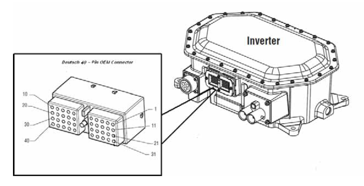
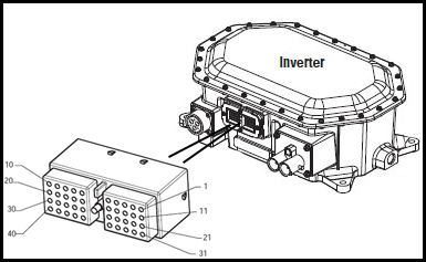
[/fusion_text][/fusion_builder_column][fusion_builder_column type=”1_1layout=”1_2spacing=”” center_content=nolink=”” target=_selfmin_height=”” hide_on_mobile=small-visibility,medium-visibility,large-visibilityclass=”” id=”” background_color=”” background_image=”” background_image_id=”” background_position=left topbackground_repeat=no-repeathover_type=noneborder_size=”0″ border_color=”” border_style=solidborder_position=allpadding_top=”” padding_right=”” padding_bottom=”” padding_left=”” margin_top=”” margin_bottom=”” animation_type=”” animation_direction=leftanimation_speed=”0.3″ animation_offset=”” last=no”][fusion_imageframe image_id=”14503|fullmax_width=”” style_type=”” blur=”” stylecolor=”” hover_type=nonebordersize=”” bordercolor=”” borderradius=”” align=centerlightbox=nogallery_id=”” lightbox_image=”” lightbox_image_id=”” alt=”paring aansluiting Deustch 19-pad” link=”” linktarget=_selfhide_on_mobile=small-visibility,medium-visibility,large-visibilityclass=”” id=”” animation_type=”” animation_direction=leftanimation_speed=”0.3″ animation_offset=””]https://www.globaltransmissionsupply.com/wp-content/uploads/mating-connector-deustch-19-way.png[/fusion_imageframe][fusion_imageframe image_id=”14504|fullmax_width=”” style_type=”” blur=”” stylecolor=”” hover_type=nonebordersize=”” bordercolor=”” borderradius=”” align=centerlightbox=nogallery_id=”” lightbox_image=”” lightbox_image_id=”” alt=”Inverter Deutsch 40-Pin connector” link=”” linktarget=_selfhide_on_mobile=small-visibility,medium-visibility,large-visibilityclass=”” id=”” animation_type=”” animation_direction=leftanimation_speed=”0.3″ animation_offset=””]https://www.globaltransmissionsupply.com/wp-content/uploads/Inverter-Deutsch-40-Pin-connector.png[/fusion_imageframe][/fusion_builder_column][fusion_builder_column type=”1_1layout=”1_1spacing=”” center_content=nolink=”” target=_selfmin_height=”” hide_on_mobile=small-visibility,medium-visibility,large-visibilityclass=”” id=”” background_image_id=”” background_color=”#000000″ background_image=”” background_position=left topundefined=”” background_repeat=no-repeathover_type=noneborder_size=”0″ border_color=”” border_style=solidborder_position=allpadding_top=”” padding_right=”” padding_bottom=”” padding_left=”” margin_top=”20″ margin_bottom=”20″ animation_type=”” animation_direction=leftanimation_speed=”0.3″ animation_offset=”” last=no”][fusion_text columns=”” column_min_width=”” column_spacing=”” rule_style=defaultrule_size=”” rule_color=”” hide_on_mobile=small-visibility,medium-visibility,large-visibilityclass=”” id=””]

NOTA: Verwys na die Eaton Hybrid komponent en Connector ligging vir Connector plekke in MY09 Systems.
[/fusion_text][/fusion_builder_column][fusion_builder_column type=”1_1layout=”1_1spacing=”” center_content=nolink=”” target=_selfmin_height=”” hide_on_mobile=small-visibility,medium-visibility,large-visibilityclass=”” id=”” background_color=”” background_image=”” background_image_id=”” background_position=left topbackground_repeat=no-repeathover_type=noneborder_size=”0″ border_color=”” border_style=solidborder_position=allpadding_top=”” padding_right=”” padding_bottom=”” padding_left=”” margin_top=”” margin_bottom=”” animation_type=”” animation_direction=leftanimation_speed=”0.3″ animation_offset=”” last=no”][fusion_imageframe image_id=”14506|fullmax_width=”” style_type=”” blur=”” stylecolor=”” hover_type=nonebordersize=”” bordercolor=”” borderradius=”” align=centerlightbox=nogallery_id=”” lightbox_image=”” lightbox_image_id=”” alt=”Inverter om PEC ” link=”” linktarget=_selfhide_on_mobile=small-visibility,medium-visibility,large-visibilityclass=”” id=”” animation_type=”” animation_direction=leftanimation_speed=”0.3″ animation_offset=””]https://www.globaltransmissionsupply.com/wp-content/uploads/Inverter-to-PEC.png[/fusion_imageframe][fusion_text columns=”” column_min_width=”” column_spacing=”” rule_style=defaultrule_size=”” rule_color=”” hide_on_mobile=small-visibility,medium-visibility,large-visibilityclass=”” id=””]

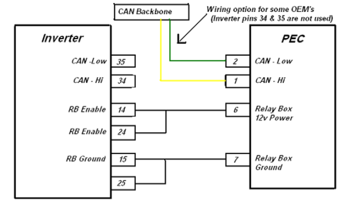
Of opsionele CAN bedraad direk aan CAN Data Link Backbone (inverter Pins 34 en 35 nie gebruik word nie):
[/fusion_text][fusion_imageframe image_id=”14505|fullmax_width=”” style_type=”” blur=”” stylecolor=”” hover_type=nonebordersize=”” bordercolor=”” borderradius=”” align=centerlightbox=nogallery_id=”” lightbox_image=”” lightbox_image_id=”” alt=”Inverter om PEC CAN Backbone” link=”” linktarget=_selfhide_on_mobile=small-visibility,medium-visibility,large-visibilityclass=”” id=”” animation_type=”” animation_direction=leftanimation_speed=”0.3″ animation_offset=””]https://www.globaltransmissionsupply.com/wp-content/uploads/Inverter-to-PEC-CAN-Backbone.png[/fusion_imageframe][/fusion_builder_column][/fusion_builder_row][/fusion_builder_container][fusion_builder_container hundred_percent=nohundred_percent_height=nohundred_percent_height_scroll=nohundred_percent_height_center_content=yesequal_height_columns=nomenu_anchor=”” hide_on_mobile=small-visibility,medium-visibility,large-visibilitystatus=publishedpublish_date=”” class=”” id=”” background_color=”” background_image=”” background_position=center centerbackground_repeat=no-repeatfade=nobackground_parallax=noneenable_mobile=noparallax_speed=”0.3″ video_mp4=”” video_webm=”” video_ogv=”” video_url=”” video_aspect_ratio=”16:9″ video_loop=yesvideo_mute=yesvideo_preview_image=”” border_size=”” border_color=”” border_style=solidmargin_top=”” margin_bottom=”” padding_top=”” padding_right=”” padding_bottom=”” padding_left=””][fusion_builder_row][fusion_builder_column type=”1_1layout=”1_1spacing=”” center_content=nolink=”” target=_selfmin_height=”” hide_on_mobile=small-visibility,medium-visibility,large-visibilityclass=”” id=”” background_color=”” background_image=”” background_image_id=”” background_position=left topbackground_repeat=no-repeathover_type=noneborder_size=”0″ border_color=”” border_style=solidborder_position=allpadding_top=”” padding_right=”” padding_bottom=”” padding_left=”” margin_top=”” margin_bottom=”” animation_type=”” animation_direction=leftanimation_speed=”0.3″ animation_offset=”” last=no”][fusion_modal name=warnings_cautionstitle=”waarskuwings & waarsku” size=largebackground=”” border_color=”” show_footer=yesclass=”” id=””]gevaar: Gevaar dui jy sal erg beseer of gedood as moenie die aangedui prosedure volg nie.
waarskuwing: Waarskuwing dui op 'n onmiddellike gevaar, wat kan lei tot ernstige persoonlike besering as jy nie die aangewese prosedure te volg.
versigtigheid: Let daarop dui voertuig of skade aan eiendom kan optree as jy nie die aangewese prosedure te volg.

nota: Nota dui addisionele detail wat sal help met die diagnose of herstel van 'n komponent / stelsel.

Volg die gespesifiseerde prosedures in die aangeduide om persoonlike beserings te voorkom:

1. As die hoë-spanning keëls is om die voertuig en die uitsluiting is geïnstalleer op die PUK, die enigste persoon wat toegelaat moet word om die voertuig begin is die persoon wat die uitsluiting tag onderteken.
2. Voor die werk op 'n voertuig of verlaat die kajuit, terwyl die enjin loop, moet jy die rathefboom in "N" plaas het die parkeerrem, en sluit die wiele.
3. Om veiligheidsredes, altyd die diens remme betrek voor die kies van rat posisies van "N."
4. Voor die aanvang van 'n voertuig altyd sit in die bestuurder se sitplek, kies "N" op die verskuiwing beheer, en stel die parkering remme.
5. In voertuie met ePTO, die enjin en / of
Motor / Generator kan begin in ePTO af. voer nooit enige onderhoud of werk op voertuig, terwyl in hierdie modus.
6. 12-Volt battery positiewe (+) en negatiewe (-) moet voor ontkoppel om enige sweiswerk op enige Hybrid toegerus voertuig.

versigtigheid: Volg die gespesifiseerde prosedures in die aangeduide om toerusting wanfunksioneer of skade te vermy.
versigtigheid: Moenie die parkeerrem nie vry te laat of te poog om 'n rat kies totdat die lugdruk is op die regte vlak.
versigtigheid: Om skade aan die oordrag tydens sleep plek die rathefboom in "N" te vermy en die opheffing van die ry wiele van die grond af of ontkoppel die aandrijflijn.

Hoë-spanning Waarskuwings & waarsku

  • Gebruik CO2 of droë chemiese brandblussers.
  • Die hoë-spanning bedrading bedek in oranje isolasie of ingewikkelde pype en gemerk met waarskuwing etikette op die verbindings.
  • Alle Eaton® Hybrid Diesel / Electric voertuie sal gemerk word "Hybrid’ aan die buitekant van die voertuig, saam met die verskuiwing etiket op die paneelbord.
  • Verwys na OEM vir spesifieke plek van onderstel gemonteer hibriede komponente.
  • MOENIE sny in die oranje hoë-spanning kabels.
  • MOENIE sny in of maak die PUK.
  • MOENIE sny in of die DC / DC Converter oop.
  • MOENIE sny in of maak die Inverter.

'N buffersone moet opgestel word en 'n hoë-spanning geïsoleerde rubberhandskoene (klas 0 met leer beskermers) is voor wat nodig is om die werk op 'n hoë-spanning. Versuim om hierdie instruksies te volg kan lei tot ernstige persoonlike besering of dood.
Die rubber geïsoleerde handskoene wat moet gedra word, terwyl die werk op die hoë-spanning stelsel is klas 0 met leer beskermers. Die rubberhandskoene moet getoets word voor elke gebruik na aanleiding van die rubber isolasie handskoene toetsprosedure gevind in "diagnostiese instrumente / Service Publications" op bladsy 6. Versuim om hierdie instruksies te volg kan lei tot ernstige persoonlike besering of dood.
Voor te inspekteer of werk op 'n hoë-spanning kabels of komponente van die "High-spanning Service Afsluiting en Power-Up Prosedure" op bladsy 4 gevolg moet word. Versuim om hierdie instruksies te volg kan lei tot ernstige persoonlike besering of dood.
Die Uitsluiting en Tagout toestelle moet net verwyder word deur die tegnikus wat die Uitsluiting en Tagout toestelle op die voertuig geplaas. Versuim om hierdie instruksies te volg kan lei tot ernstige persoonlike besering of dood.
Hoë-spanning rubber geïsoleerde handskoene (klas 0 met leer beskermers) moet gedra word wanneer daar op 'n
hoë-spanning kabels. Die "Hoogspannings Service Afsluiting en Power-Up Prosedure" op bladsy 4 moet voor wat gevolg moet word om die verwydering van 'n hoë-spanning kabels. Versuim om hierdie instruksies te volg kan lei tot ernstige persoonlike besering of dood.
Hoë-spanning kabels en bedrading is oranje en bevat 'n waarskuwing etiket op die verbindings. Hoë-spanning komponente gemerk met 'n etiket. Hoë-spanning rubber geïsoleerde handskoene (klas 0 met leer beskermers) moet gebruik word wanneer daar op enige van hierdie komponente. Versuim om hierdie instruksies te volg kan lei tot ernstige persoonlike besering of dood.

Hoë-spanning Service Shutdown Prosedures

Hoë-spanning Service Afsluiting en Power-Up Prosedure1. Volg "Hoogspannings Werk Area" prosedure.
2. Vind die rooi PEC Service Skakel die voorkant van die PAC en stoot afskakel.
3. Verwyder die Diens Skakel Cover en installeer die Uitsluiting Bracket (J48506).
4. Vas tag om die Uitsluiting Bracket.
5. Verseker die PUK Service Switch kan nie beweeg van die af posisie.
6. Laat die stelsel op te rig vir 'n minimum van 5 minute om 'n hoë spanning ontlaai.
7. Verbind ServiceRanger en kyk na die data Monitor PID 116 genaamd "High-spanning Potensiële Battery." Gebruik SPN 520323 vir J1939 verband "Battery Voltage RB" (Relay Box).
8. Die spanning moet wees 30 volts of minder. As die spanning is bo 30 volts, werk nie op die voertuig en kontak Eaton® by 1-800-826-HELP (4357).
9. Draai aansitsleutel af en gaan na herstel of stap probleem op te los.
nota: Die spanning daal tot nul wanneer die sleutel is af.

Hoë-spanning Service Power-Up Prosedure

1. Installeer al 'n hoë-spanning verbindings in hul toegesluit posisies.
2. As jy die persoon wat op die voertuig, verwyder die Uitsluiting Bracket en tag.
3. Installeer die Uitsluiting Bracket oor die Diens Skakel.
4. Trek die Diens Skakel uit en laat voertuig stel vir 2 minute.
5. Start vehicle when appropriate.[/fusion_modal][fusion_modal name=component_locationtitle=”Eaton Hybrid komponent en Connector ligging ” size=largebackground=”#ffffffborder_color=”” show_footer=yesclass=”” id=””]

Eaton Hybrid komponent en Connector Locations MY08 Systems

[/fusion_modal][fusion_modal name=component_location2title=”Eaton Hybrid komponent en Connector ligging MY09 Systems” size=largebackground=”#ffffffborder_color=”” show_footer=yesclass=”” id=””]

Eaton Hybrid komponent en Connector Locations MY09 Systems

[/fusion_modal][/fusion_builder_column][/fusion_builder_row][/fusion_builder_container][fusion_builder_container hundred_percent=nohundred_percent_height=nohundred_percent_height_scroll=nohundred_percent_height_center_content=yesequal_height_columns=nomenu_anchor=”” hide_on_mobile=small-visibility,medium-visibility,large-visibilitystatus=publishedpublish_date=”” class=”” id=”” background_color=”” background_image=”” background_position=center centerbackground_repeat=no-repeatfade=nobackground_parallax=noneenable_mobile=noparallax_speed=”0.3″ video_mp4=”” video_webm=”” video_ogv=”” video_url=”” video_aspect_ratio=”16:9″ video_loop=yesvideo_mute=yesvideo_preview_image=”” border_size=”” border_color=”” border_style=solidmargin_top=”” margin_bottom=”” padding_top=”” padding_right=”” padding_bottom=”” padding_left=””][fusion_builder_row][fusion_builder_column type=”1_1layout=”1_1spacing=”” center_content=nolink=”” target=_selfmin_height=”” hide_on_mobile=small-visibility,medium-visibility,large-visibilityclass=”” id=”” background_color=”” background_image=”” background_image_id=”” background_position=left topbackground_repeat=no-repeathover_type=noneborder_size=”0″ border_color=”” border_style=solidborder_position=allpadding_top=”” padding_right=”” padding_bottom=”” padding_left=”” margin_top=”” margin_bottom=”” animation_type=”” animation_direction=leftanimation_speed=”0.3″ animation_offset=”” last=no”][fusion_content_boxes layout=clean-horizontalcolumns=”1″ title_size=”18pxheading_size=”3″ title_color=”#ffffffbody_color=”#ffffffbackgroundcolor=”#4f4f4ficon=”” iconflip=”” iconrotate=”” iconspin=noiconcolor=”” icon_circle=”” icon_circle_radius=”” circlecolor=”” circlebordersize=”” circlebordercolor=”” outercirclebordersize=”” outercirclebordercolor=”” icon_size=”” icon_hover_type=”” hover_accent_color=”” image=”” image_id=”” image_width=”” image_height=”” link_type=”” button_span=”” link_area=”” link_target=”” icon_align=leftanimation_type=”” animation_delay=”” animation_offset=”” animation_direction=leftanimation_speed=”0.3″ margin_top=”” margin_bottom=”” hide_on_mobile=small-visibility,medium-visibility,large-visibilityclass=”” id=””][fusion_content_box title=STAP 1. Check vir Active of Stil skuld-kode status en kyk HCM konfigurasies.backgroundcolor=”” icon=”” iconflip=”” iconrotate=”” iconspin=noiconcolor=”” circlecolor=”” circlebordersize=”” circlebordercolor=”” outercirclebordersize=”” outercirclebordercolor=”” image=”” image_id=”” image_width=”” image_height=”” link=”” linktext=”Lees meer” link_target=”” animation_type=”” animation_direction=leftanimation_speed=”0.3″ animation_offset=””]

  1. Haal aktiewe foutkodes en FMI's op met ServiceRanger deur die 9-rigting diagnostiese koppelstuk of handmatig te gebruik.
  2. Voer Elektriese voortoets en Hybrid Elektriese voortoets.
    • As geen probleme is gevind tydens óf elektriese toets, gaan na Stap 2.
    • As kwessie is herstel tydens óf elektriese toets, gaan na Stap 10.

[/fusion_content_box][/fusion_content_boxes][fusion_content_boxes layout=clean-horizontalcolumns=”1″ title_size=”18pxheading_size=”3″ title_color=”#ffffffbody_color=”#ffffffbackgroundcolor=”#4f4f4ficon=”” iconflip=”” iconrotate=”” iconspin=noiconcolor=”” icon_circle=”” icon_circle_radius=”” circlecolor=”” circlebordersize=”” circlebordercolor=”” outercirclebordersize=”” outercirclebordercolor=”” icon_size=”” icon_hover_type=”” hover_accent_color=”” image=”” image_id=”” image_width=”” image_height=”” link_type=”” button_span=”” link_area=”” link_target=”” icon_align=leftanimation_type=”” animation_delay=”” animation_offset=”” animation_direction=leftanimation_speed=”0.3″ margin_top=”” margin_bottom=”” hide_on_mobile=small-visibility,medium-visibility,large-visibilityclass=”” id=””][fusion_content_box title=STAP 2. Verifieer kontinuïteit van PEC kringe.backgroundcolor=”” icon=”” iconflip=”” iconrotate=”” iconspin=noiconcolor=”” circlecolor=”” circlebordersize=”” circlebordercolor=”” outercirclebordersize=”” outercirclebordercolor=”” image=”” image_id=”” image_width=”” image_height=”” link=”” linktext=”Lees meer” link_target=”” animation_type=”” animation_direction=leftanimation_speed=”0.3″ animation_offset=””]

  1. sleutel af.
    gevaar: sien Hoë-spanning Service Afsluiting en Power-Up Prosedure. Volg die prosedures om skok te voorkom, brand of dood van onbehoorlik hanteer hoë-spanning.
  2. Ontkoppel PEC 19-Way Connector.
  3. Meet weerstand op PEC 19-Way OEM draad span Connector Pin 1 en Pin 2:
    nota: Maak seker dat die volt / ohm meter is op die regte skaal (rondom 200 ohm skaal).

    • As weerstand tussen Pin 1 en Pin 2 is tussen 50-70 ohm, gaan na Stap 3.
    • As weerstand is buite bereik, gaan na Stap 7.

[/fusion_content_box][/fusion_content_boxes][fusion_content_boxes layout=clean-horizontalcolumns=”1″ title_size=”18pxheading_size=”3″ title_color=”#ffffffbody_color=”#ffffffbackgroundcolor=”#4f4f4ficon=”” iconflip=”” iconrotate=”” iconspin=noiconcolor=”” icon_circle=”” icon_circle_radius=”” circlecolor=”” circlebordersize=”” circlebordercolor=”” outercirclebordersize=”” outercirclebordercolor=”” icon_size=”” icon_hover_type=”” hover_accent_color=”” image=”” image_id=”” image_width=”” image_height=”” link_type=”” button_span=”” link_area=”” link_target=”” icon_align=leftanimation_type=”” animation_delay=”” animation_offset=”” animation_direction=leftanimation_speed=”0.3″ margin_top=”” margin_bottom=”” hide_on_mobile=small-visibility,medium-visibility,large-visibilityclass=”” id=””][fusion_content_box title=STAP 3. Verifieer CAN kring vir 'n kort om gemaalde.backgroundcolor=”” icon=”” iconflip=”” iconrotate=”” iconspin=noiconcolor=”” circlecolor=”” circlebordersize=”” circlebordercolor=”” outercirclebordersize=”” outercirclebordercolor=”” image=”” image_id=”” image_width=”” image_height=”” link=”” linktext=”Lees meer” link_target=”” animation_type=”” animation_direction=leftanimation_speed=”0.3″ animation_offset=””]

  1. Meet weerstand tussen PEC 19-Way OEM draad span Connector Pin 1 en grond en tussen Pin 2 en grond:
    • As óf weerstand is 0-100 ohm, herstel OEM KAN bedrading kring. gaan na Stap 10.
    • As beide weerstande is 7k ohm, gaan na Stap 4.

[/fusion_content_box][/fusion_content_boxes][fusion_content_boxes layout=clean-horizontalcolumns=”1″ title_size=”18pxheading_size=”3″ title_color=”#ffffffbody_color=”#ffffffbackgroundcolor=”#4f4f4ficon=”” iconflip=”” iconrotate=”” iconspin=noiconcolor=”” icon_circle=”” icon_circle_radius=”” circlecolor=”” circlebordersize=”” circlebordercolor=”” outercirclebordersize=”” outercirclebordercolor=”” icon_size=”” icon_hover_type=”” hover_accent_color=”” image=”” image_id=”” image_width=”” image_height=”” link_type=”” button_span=”” link_area=”” link_target=”” icon_align=leftanimation_type=”” animation_delay=”” animation_offset=”” animation_direction=leftanimation_speed=”0.3″ margin_top=”” margin_bottom=”” hide_on_mobile=small-visibility,medium-visibility,large-visibilityclass=”” id=””][fusion_content_box title=STAP 4. Verifieer CAN is bevolk in korrekte Connector Pin.backgroundcolor=”” icon=”” iconflip=”” iconrotate=”” iconspin=”” iconcolor=”” circlecolor=”” circlebordersize=”” circlebordercolor=”” outercirclebordersize=”” outercirclebordercolor=”” image=”” image_id=”” image_width=”” image_height=”” link=”” linktext=”” link_target=”” animation_type=”” animation_direction=leftanimation_speed=”0.3″ animation_offset=””]

  1. Meet weerstand tussen PEC 19-Way Connector Pin 1 en Inverter 40-Way Connector Pin 4:
    • As weerstand is 0-0,3 ohm, gaan na Stap 5.
    • As weerstand is 60 ohm, herstel kan Bedrading (hi en lae is verkeerd bedraad), dan gaan na Stap 10.

[/fusion_content_box][/fusion_content_boxes][fusion_content_boxes layout=clean-horizontalcolumns=”1″ title_size=”18pxheading_size=”3″ title_color=”#ffffffbody_color=”#ffffffbackgroundcolor=”#4f4f4ficon=”” iconflip=”” iconrotate=”” iconspin=noiconcolor=”” icon_circle=”” icon_circle_radius=”” circlecolor=”” circlebordersize=”” circlebordercolor=”” outercirclebordersize=”” outercirclebordercolor=”” icon_size=”” icon_hover_type=”” hover_accent_color=”” image=”” image_id=”” image_width=”” image_height=”” link_type=”” button_span=”” link_area=”” link_target=”” icon_align=leftanimation_type=”” animation_delay=”” animation_offset=”” animation_direction=leftanimation_speed=”0.3″ margin_top=”” margin_bottom=”” hide_on_mobile=small-visibility,medium-visibility,large-visibilityclass=”” id=””][fusion_content_box title=STAP 5. Verifieer krag en grond te PEC.backgroundcolor=”” icon=”” iconflip=”” iconrotate=”” iconspin=”” iconcolor=”” circlecolor=”” circlebordersize=”” circlebordercolor=”” outercirclebordersize=”” outercirclebordercolor=”” image=”” image_id=”” image_width=”” image_height=”” link=”” linktext=”” link_target=”” animation_type=”” animation_direction=leftanimation_speed=”0.3″ animation_offset=””]

  1. Installeer 40-Way Connector by Inverter.
  2. sleutel op.
  3. Measure for voltage on PEC 19-Way OEM Wire Harness Connector Pins 6 en 7:
    • As Pins 6 en 7 have battery voltage (12 volts +/ – 1.2 volts), vervang die PUK, dan gaan na Stap 10.
    • As penne 6 en 7 het geen spanning of minder as 1.2 volts van die battery spanning, gaan na Stap 6.

[/fusion_content_box][/fusion_content_boxes][fusion_content_boxes layout=clean-horizontalcolumns=”1″ title_size=”18pxheading_size=”3″ title_color=”#ffffffbody_color=”#ffffffbackgroundcolor=”#4f4f4ficon=”” iconflip=”” iconrotate=”” iconspin=noiconcolor=”” icon_circle=”” icon_circle_radius=”” circlecolor=”” circlebordersize=”” circlebordercolor=”” outercirclebordersize=”” outercirclebordercolor=”” icon_size=”” icon_hover_type=”” hover_accent_color=”” image=”” image_id=”” image_width=”” image_height=”” link_type=”” button_span=”” link_area=”” link_target=”” icon_align=leftanimation_type=”” animation_delay=”” animation_offset=”” animation_direction=leftanimation_speed=”0.3″ margin_top=”” margin_bottom=”” hide_on_mobile=small-visibility,medium-visibility,large-visibilityclass=”” id=””][fusion_content_box title=STAP 6. Verifieer kontinuïteit tussen Inverter en PAC.backgroundcolor=”” icon=”” iconflip=”” iconrotate=”” iconspin=”” iconcolor=”” circlecolor=”” circlebordersize=”” circlebordercolor=”” outercirclebordersize=”” outercirclebordercolor=”” image=”” image_id=”” image_width=”” image_height=”” link=”” linktext=”” link_target=”” animation_type=”” animation_direction=leftanimation_speed=”0.3″ animation_offset=””]

  1. sleutel af.
  2. Verwyder Inverter 40-Way Connector.40 pen connector aan inverter Eaton voller oordrag
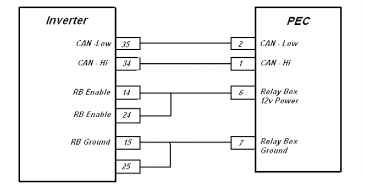
  3. Meet weerstand op OEM 40-Way Inverter Connector Pin 14 OEM 19-Way PEC Connector Pin 6 en Inverter Connector Pin 15 om PEC Connector Pin 7: 19 pen connector-40-pen-aansluiting
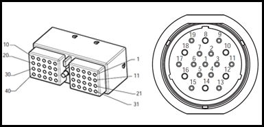
    • As weerstand van Pin 14 om Pin 6 is 0-0,3 ohm, en weerstand van Pin 15 om Pin 7 is 0-0,3 ohm (kyk ook terminale spanning op Pins), vervang die Inverter, dan gaan na Stap 7.
      ?? As weerstand is OL of buite reeks, herstel OEM draad span tussen Inverter en PAC, dan gaan na Stap 10.

[/fusion_content_box][/fusion_content_boxes][fusion_content_boxes layout=clean-horizontalcolumns=”1″ title_size=”18pxheading_size=”3″ title_color=”#ffffffbody_color=”#ffffffbackgroundcolor=”#4f4f4ficon=”” iconflip=”” iconrotate=”” iconspin=noiconcolor=”” icon_circle=”” icon_circle_radius=”” circlecolor=”” circlebordersize=”” circlebordercolor=”” outercirclebordersize=”” outercirclebordercolor=”” icon_size=”” icon_hover_type=”” hover_accent_color=”” image=”” image_id=”” image_width=”” image_height=”” link_type=”” button_span=”” link_area=”” link_target=”” icon_align=leftanimation_type=”” animation_delay=”” animation_offset=”” animation_direction=leftanimation_speed=”0.3″ margin_top=”” margin_bottom=”” hide_on_mobile=small-visibility,medium-visibility,large-visibilityclass=”” id=””][fusion_content_box title=STAP 7. Verifieer CAN by PUK met Inverter.backgroundcolor=”” icon=”” iconflip=”” iconrotate=”” iconspin=”” iconcolor=”” circlecolor=”” circlebordersize=”” circlebordercolor=”” outercirclebordersize=”” outercirclebordercolor=”” image=”” image_id=”” image_width=”” image_height=”” link=”” linktext=”” link_target=”” animation_type=”” animation_direction=leftanimation_speed=”0.3″ animation_offset=””]

  1. sleutel af.
  2. Verwyder Inverter 40-Way Connector.40 Manier aansluiting by inverter
  3. Check OEM Inverter Connector vir Pins 34 en 35. Indien geen penne bevolk in aansluiting, die PAC CAN Kommunikasie gaan CAN Backbone, nie die Inverter:
    • As Pin 34 en Pin 35 is nie bevolk, gaan na Stap 9.
    • As OEM Inverter Connector het Pins 34 en 35, gaan na Stap 8.

[/fusion_content_box][/fusion_content_boxes][fusion_content_boxes layout=clean-horizontalcolumns=”1″ title_size=”18pxheading_size=”3″ title_color=”#ffffffbody_color=”#ffffffbackgroundcolor=”#4f4f4ficon=”” iconflip=”” iconrotate=”” iconspin=noiconcolor=”” icon_circle=”” icon_circle_radius=”” circlecolor=”” circlebordersize=”” circlebordercolor=”” outercirclebordersize=”” outercirclebordercolor=”” icon_size=”” icon_hover_type=”” hover_accent_color=”” image=”” image_id=”” image_width=”” image_height=”” link_type=”” button_span=”” link_area=”” link_target=”” icon_align=leftanimation_type=”” animation_delay=”” animation_offset=”” animation_direction=leftanimation_speed=”0.3″ margin_top=”” margin_bottom=”” hide_on_mobile=small-visibility,medium-visibility,large-visibilityclass=”” id=””][fusion_content_box title=STAP 8. Verifieer kontinuïteit tussen Inverter kringe en PAC kringe.backgroundcolor=”” icon=”” iconflip=”” iconrotate=”” iconspin=”” iconcolor=”” circlecolor=”” circlebordersize=”” circlebordercolor=”” outercirclebordersize=”” outercirclebordercolor=”” image=”” image_id=”” image_width=”” image_height=”” link=”” linktext=”” link_target=”” animation_type=”” animation_direction=leftanimation_speed=”0.3″ animation_offset=””]

  1. Meet weerstand tussen Inverter 40-Way Connector Pin 34 en OEM 19-Way PEC Connector Pin 1 en Inverter 40-Way Connector Pin 35 en PUK 19-Way Connector Pin 2:19 pen connector-40-pen-aansluitingnota: Maak seker dat die volt / ohm meter is op die regte skaal (rondom 200 ohm skaal)
    • As weerstand tussen Pin 34 en Pin 1 is tussen 0-0,3 ohm, en weerstand tussen Pin 35 en Pin 2 is tussen 0-0,3 ohm, vervang die Inverter. Sien MY09 Inverter Verwydering en installasie), dan gaan na Stap 10.
    • As weerstand is OL of buite reeks, herstel OEM draad span tussen Inverter en PAC, dan gaan na Stap 10.

[/fusion_content_box][/fusion_content_boxes][fusion_content_boxes layout=clean-horizontalcolumns=”1″ title_size=”18pxheading_size=”3″ title_color=”#ffffffbody_color=”#ffffffbackgroundcolor=”#4f4f4ficon=”” iconflip=”” iconrotate=”” iconspin=noiconcolor=”” icon_circle=”” icon_circle_radius=”” circlecolor=”” circlebordersize=”” circlebordercolor=”” outercirclebordersize=”” outercirclebordercolor=”” icon_size=”” icon_hover_type=”” hover_accent_color=”” image=”” image_id=”” image_width=”” image_height=”” link_type=”” button_span=”” link_area=”” link_target=”” icon_align=leftanimation_type=”” animation_delay=”” animation_offset=”” animation_direction=leftanimation_speed=”0.3″ margin_top=”” margin_bottom=”” hide_on_mobile=small-visibility,medium-visibility,large-visibilityclass=”” id=””][fusion_content_box title=STAP 9. Verifieer kontinuïteit tussen PUK kan en Backbone.backgroundcolor=”” icon=”” iconflip=”” iconrotate=”” iconspin=”” iconcolor=”” circlecolor=”” circlebordersize=”” circlebordercolor=”” outercirclebordersize=”” outercirclebordercolor=”” image=”” image_id=”” image_width=”” image_height=”” link=”” linktext=”” link_target=”” animation_type=”” animation_direction=leftanimation_speed=”0.3″ animation_offset=””]

  1. As die inverter 40-pen connector nie Pins het nie 34 en 35 bevolk dan die CAN kommunikasie tak tot 19-Way Connector by die PUK is direk bedraad om CAN Backbone:
    • Herstel OEM draad span tussen die PAC en die CAN Kommunikasie Backbone, dan gaan na Stap 10.

[/fusion_content_box][/fusion_content_boxes][fusion_content_boxes layout=clean-horizontalcolumns=”1″ title_size=”18pxheading_size=”3″ title_color=”#ffffffbody_color=”#ffffffbackgroundcolor=”#4f4f4ficon=”” iconflip=”” iconrotate=”” iconspin=noiconcolor=”” icon_circle=”” icon_circle_radius=”” circlecolor=”” circlebordersize=”” circlebordercolor=”” outercirclebordersize=”” outercirclebordercolor=”” icon_size=”” icon_hover_type=”” hover_accent_color=”#f41000image=”” image_id=”” image_width=”” image_height=”” link_type=”” button_span=”” link_area=”” link_target=”” icon_align=leftanimation_type=”” animation_delay=”” animation_offset=”” animation_direction=leftanimation_speed=”0.3″ margin_top=”” margin_bottom=”” hide_on_mobile=small-visibility,medium-visibility,large-visibilityclass=”” id=””][fusion_content_box title=STAP 10. verifieer herstel.backgroundcolor=”” icon=”” iconflip=”” iconrotate=”” iconspin=noiconcolor=”” circlecolor=”” circlebordersize=”” circlebordercolor=”” outercirclebordersize=”” outercirclebordercolor=”” image=”” image_id=”” image_width=”” image_height=”” link=”” linktext=”Lees meer” link_target=”” animation_type=”” animation_direction=leftanimation_speed=”0.3″ animation_offset=””]

  1. sleutel af.
  2. Herkonnekteer al verbindings en die negatiewe battery kabel.
  3. sleutel op.
  4. duidelik kodes, sien Duidelik Stil Foute.
  5. Ry die voertuig en probeer om die kode te herstel.
  6. Check vir kodes, sien Kyk Active en Stil Foute.
    • Indien geen kodes, toets is voltooi.
    • As skuld Kode 89 verskyn, vind fout in die toets, gaan na Stap 1.
    • As 'n kode buiten 89 verskyn, sien Fout Kode Index Lys.

[/fusion_content_box][/fusion_content_boxes][/fusion_builder_column][/fusion_builder_row][/fusion_builder_container][fusion_global id=”13788″]