إيتون فولار الهجين نقل رمز خطأ 33 – انخفاض الجهد البطارية (TECU)
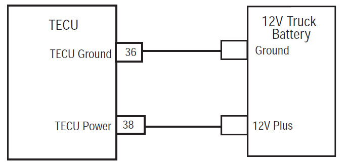
خطأ رمز لايتون الهجين نماذج أنظمة القيادة (MY08) EH-8E306A-U, EH-8E306A-UPG, EH-8E306A-UP, EH-8E306A-CD, EH-8E306A-T, EH-6E606B-CD, (MY09) EH-8E406A-U / P, EH-8E406A-UP, EH-8E406A-UPG, EH-8E406A-CD, EH-8E406A-CDG, EH-8E406A مجلس الإنماء والإعمار, EH-8E406A-T, EH-6E706B-CD, EH-6E706B-P وEH-6E706B-UPG. وحدة التحكم بالإرسال الالكترونية (TECU) هي التي شنت على نقل ويحتوي على برنامج للتحكم في عملية انتقال; ومع ذلك, وحدة التحكم الهجين (HCM) يتحكم في تشغيل TECU خلال عملية وضع هجين العادية. طاقة البطارية الرئيسية HCM هي تنصهر تغذية 12 فولت الذي يمر عبر HCM 38 طريق موصل السيارة مع السلك الأرضي الرئيسي يعود إلى الطرف السالب البطارية.
خطأ مدونة 33 – انخفاض الجهد البطارية (TECU) كشف
يجب أن تتحقق الشروط التالية قبل النظام بالكشف عن خطأ:
- TECU اشتعال الجهد أكبر من 7 فولت وأقل من 16 فولت.
شروط تعيين رمز خطأ النشطة
- صندوق النقد الدولي 4 ومن المقرر عندما يسقط TECU الجهد البطارية أدناه 7 فولت لأكثر من 1 ثانيا.
تراجع عندما رمز خطأ 33 ومن المقرر تحدث الشروط التالية:
- يتم تخزين خطأ في الذاكرة TECU.
- تضاء لا أضواء على زر ضغط.
- في حالة حدوث هذا الخطأ قبل السلطة حتى, السيارة لن كرنك.
- إذا حدث هذا الخطأ أثناء القيادة, وتحتفظ السيارة والعتاد الحالي. مخلب يفتح عند توقف السيارة.
شروط محدد خطأ قانون غير فعال
فقط أخطاء الخاملة يمكن إزالتها من وحدة التحكم بالإرسال الالكترونية (TECU) أو HCM التاريخ باستخدام ServiceRanger. وTECU يزيل تلقائيا أخطاء من التاريخ بعد 200 وكانت ساعات وHCM مسح أخطاء من التاريخ بعد خطأ تلقائيا غير نشطة لل 200 ساعات.
يمكن أن يكون سبب هذا رمز خطأ من قبل أي من الحالات التالية:
- صندوق النقد الدولي 4
- إمدادات الطاقة لTECU
- بطاريات منخفضة أو سيئة اتصال الطاقة الرئيسي
- نظام الشحن
- TECU
خطأ مدونة 33 – منخفضة بطارية اختبار الجهد
نظام مكون تحديد MY08:
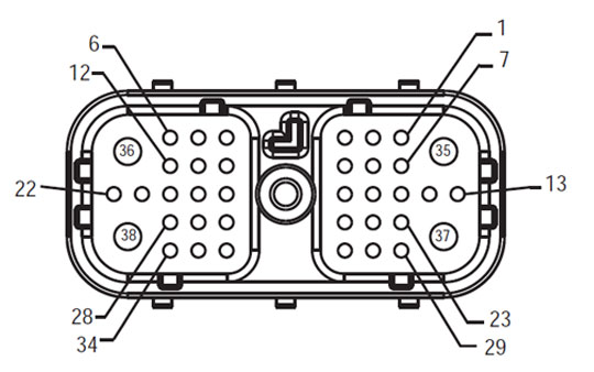
تسخير جبهة الشخصي (TECU – مركبات واجهة موصل)
ملحوظة: الرجوع إلى إيتون مكون الهجين ورابط الموقع للموصل المواقع الموجودة في أنظمة MY08
ملحوظة: الرجوع إلى إيتون مكون الهجين ورابط الموقع للموصل المواقع الموجودة في أنظمة MY09.
تحذيرات &أمبير; التحذيرات
خطر: يشير الخطر الذي سيتم بجروح خطيرة أو قتل إذا لم يتم اتباع الإجراءات المشار إليها.
تحذير: يشير التحذير من خطر فوري, مما قد يؤدي إلى الإصابة الشخصية وخيمة إذا كنت لا اتبع الإجراء المشار إليه.
الحذر: يشير الحذر يمكن أن تحدث السيارة أو أضرار في الممتلكات إذا كنت لا اتبع الإجراء المشار إليه.
ملحوظة: ملاحظة تشير تفاصيل إضافية من شأنها أن تساعد في التشخيص أو إصلاح مكون / نظام.
اتبع الإجراءات المحددة في الترتيب المشار إليه لتجنب الإصابة الشخصية:
1. إذا المخاريط ذات الجهد العالي هي حول السيارة ويتم تثبيت تأمين على PEC, الشخص الوحيد الذي ينبغي أن يسمح لبدء تشغيل السيارة هو الشخص الذي وقع العلامة تأمين.
2. قبل أن تبدأ العمل على سيارة أو مغادرة الكابينة في حين أن المحرك يعمل, يجب وضع ذراع ناقل الحركة في "N" ضبط فرامل اليد, ومنع العجلات.
3. لأسباب تتعلق بالسلامة, دائما إشراك فرامل الخدمة قبل اختيار المواقف والعتاد من "N."
4. قبل البدء في السيارة دائما أن يجلسوا في مقعد السائق, حدد "N" على السيطرة تحول, وتعيين الفرامل وقوف السيارات.
5. في السيارات مع ePTO, المحرك و / أو
محرك / مولد يمكن أن تبدأ في وضع ePTO. أبدا إجراء أي صيانة أو العمل على سيارة, بينما في هذا الوضع.
6. 12-فولت بطارية إيجابية (+) والسلبية (-) يجب فصل قبل أي لحام على أي مركبة مجهزة الهجين.
الحذر: اتبع الإجراءات المحددة في الترتيب المشار إليه لتجنب عطل المعدات أو أضرار.
الحذر: لا تعفي فرامل اليد أو محاولة تحديد العتاد حتى ضغط الهواء في المستوى الصحيح.
الحذر: لتجنب الأضرار التي لحقت نقل خلال سحب مكان عتلة التغيير في "N" ورفع العجلات بالسيارة من الأرض أو فصل مجموعة الحركة.
تحذيرات ذات الجهد العالي & التحذيرات
- استخدام CO2 أو جاف الكيميائية طفايات الحريق.
- وتغطي الأسلاك عالية الجهد في العزل البرتقال أو الأنابيب الملتوية ووضع علامة مع علامات تحذير في الموصلات.
- يتم وضع علامة كافة Eaton® الهجين الديزل سيارات / الكهربائية "الهجين’ على السطح الخارجي للسيارة, جنبا إلى جنب مع التسمية التحول على اندفاعة.
- الرجوع إلى OEM لموقع معين من الهيكل شنت المكونات الهجينة.
- لا قطع في كابلات ذات الجهد العالي البرتقال.
- لا يقتطع أو فتح PEC.
- لا يقتطع أو فتح محول DC / DC.
- لا يقتطع أو فتح العاكس.
يجب اقامة منطقة عازلة حتى وذات الجهد العالي المعزولة قفازات مطاطية (صف دراسي 0 مع حماة الجلود) مطلوبة قبل العمل على الفولت العالى. قد يؤدي عدم اتباع هذه التعليمات يؤدي إلى حدوث إصابات خطيرة أو الموت.
القفازات المطاطية العازلة التي يجب أن ترتديه في الوقت الذي تعمل على نظام الضغط العالي من الدرجة 0 مع حماة الجلود. يجب اختبار قفازات مطاطية قبل كل استخدام باتباع الإجراء قفازات مطاطية عازلة للاختبار وجدت في "أدوات التشخيص / المنشورات الخدمة" في صفحة 6. قد يؤدي عدم اتباع هذه التعليمات يؤدي إلى حدوث إصابات خطيرة أو الموت.
قبل تفتيش أو يعملون في أي الكابلات ذات الجهد العالي أو مكونات "الإجراءات ذات الجهد العالي إيقاف خدمة والطاقة الهاتفي" في صفحة 4 يجب ان يتبع. قد يؤدي عدم اتباع هذه التعليمات يؤدي إلى حدوث إصابات خطيرة أو الموت.
يجب إزالة الأجهزة تأمين وTagout فقط من قبل فني التي وضعت الأجهزة تأمين وTagout على السيارة. قد يؤدي عدم اتباع هذه التعليمات يؤدي إلى حدوث إصابات خطيرة أو الموت.
عالية الجهد المطاط معزول قفازات (صف دراسي 0 مع حماة الجلود) يجب أن ترتديه عند العمل على أي
الكابلات ذات الجهد العالي. و"إيقاف عالية الجهد خدمة والسلطة حتى إجراء" على الصفحة 4 يجب اتباعها قبل إزالة أي الكابلات ذات الجهد العالي. قد يؤدي عدم اتباع هذه التعليمات يؤدي إلى حدوث إصابات خطيرة أو الموت.
الكابلات ذات الجهد العالي والأسلاك هي البرتقال وتحتوي على بطاقة التحذير في الموصلات. يتم وضع علامة مكونات عالية الجهد مع تسمية. عالية الجهد المطاط معزول قفازات (صف دراسي 0 مع حماة الجلود) يجب أن تستخدم عند العمل على أي من هذه المكونات. قد يؤدي عدم اتباع هذه التعليمات يؤدي إلى حدوث إصابات خطيرة أو الموت.
عالية الجهد إجراءات خدمة إيقاف
 1. اتبع "عالية الجهد منطقة العمل" الإجراء.
2. تحديد موقع خدمة تبديل PEC الأحمر على الجزء الأمامي من PEC ودفع إيقاف.
3. إزالة الغطاء خدمة تبديل وتثبيت القوس تأمين (J48506).
4. العلامة ربط لتأمين القوس.
5. ضمان خدمة تبديل PEC لا يمكن الانتقال من وضع إيقاف التشغيل.
6. السماح للنظام لضبط مدة لا تقل عن 5 دقيقة لتصريف الجهد العالي.
7. ربط ServiceRanger وعرض مراقب PID البيانات 116 ودعا "عالية الجهد إمكانية البطارية." استخدام SPN 520323 للاتصال J1939 "بطارية الجهد RB" (صندوق النقل).
8. يجب أن يكون الجهد 30 فولت أو أقل. إذا كان الجهد فوق 30 فولت, لا تعمل على السيارة والاتصال Eaton® في 1-800-826-HELP (4357).
9. تسليم مفتاح الإشعال قبالة، والشروع في إصلاح أو خطوة استكشاف الأخطاء وإصلاحها.
ملحوظة: الجهد ينخفض إلى الصفر عندما يكون المفتاح هو خارج.
عالية الجهد خدمة السلطة حتى إجراء
1. تثبيت كافة الموصلات عالية الجهد في المناصب أقفالها.
2. إذا كنت الشخص يعمل على السيارة, إزالة تأمين القوس وعلامة.
3. إعادة تثبيت تأمين القوس على خدمة تبديل.
4. سحب خدمة تبديل خارج وترك مجموعة سيلة ل 2 الدقائق.
5. بدء السيارة عند الاقتضاء.
إيتون مكون الهجين ورابط الموقع

إيتون مكون الهجين ورابط الموقع الأنظمة MY09

خطوة 1. تحقق من وضع رمز خطأ نشطة أو غير نشطة وأداء الاختبار القبلي الكهربائية.
- استرداد رموز خطأ النشطة ونظام معلومات الإدارة المالية مع ServiceRanger باستخدام موصل التشخيص 9-الطريق.
- أداء الاختبار القبلي الكهربائية.
- إذا رمز خطأ 33 نشط بعد أداء الاختبار القبلي الكهربائية, استبدال وحدة الإرسال التحكم الإلكترونية (TECU) (إلا إذا رمز خطأ غير نشط), ثم انتقل إلى الخطوة 2.
• إذا كان رمز خطأ 33 غير نشط بعد أداء الاختبار القبلي الكهربائية, رموز واضحة وانتقل إلى الخطوة 2.
- إذا رمز خطأ 33 نشط بعد أداء الاختبار القبلي الكهربائية, استبدال وحدة الإرسال التحكم الإلكترونية (TECU) (إلا إذا رمز خطأ غير نشط), ثم انتقل إلى الخطوة 2.
خطوة 2. تحقق من إصلاح.
- من رئيسي.
- إعادة كافة الروابط وكابل البطارية السلبي.
- مفتاح على.
- رموز واضحة, نرى أخطاء واضحة الخاملة.
- قيادة السيارة ومحاولة لإعادة رمز.
- التحقق من وجود رموز, نرى عرض أخطاء النشطة وغير النشطة.
- إذا لم يكن هناك رموز, اختبار اكتمال.
- إذا رمز خطأ 3 يبدو, وجدت خطأ في اختبار, انتقل إلى الخطوة 1.
- إذا رمز غير 3 يبدو, نرى خطأ قائمة مؤشر كود.
أي انتقال جزء تحتاج لدينا ذلك! الشحن نفس اليوم متاح, في جميع أنحاء العالم.
تحتاج إلى دعم مجاني من أحد خبرائنا?