
Driveline Angularity Troubleshooting
Torsional Vibration
Checking Driveline U-Joint Operation Angles
The action of a driveline with a universal joint at either end working through an angle results in a peculiar motion. The driveline will speed up and slow down twice for each revolution. If the working angles at either end of the shaft are unequal, torsional vibration results. This torsional vibration will tend to cancel itself out if both joint working angles are equal.
Types of Noise
Noise or vibration which occurs only at certain road speeds and diminishes as speed increases is generally caused by unequal working angles of driveline joints. Noise or vibration which is persistent throughout the speed range and varies in intensity with change of speed may be caused by unbalanced drivelines, unbalanced brake drums or discs, or drivelines with universal joints out of phase.
Preliminary Checks
Make checks of the following before taking angle readings:
- Check companion flange or yoke nut for looseness and torque to proper specification if necessary.
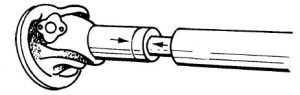
- Driveline slip joints that do not have the arrows or other markings pointing to each other will result in the driveline universal joints being out of phase. In other words, the transmission universal joint may be turned one spline or more to the right or left of being aligned with the universal joint at the opposite end of the driveline.
- Some computer designed drivelines are purposely built with U-joints out of phase. Check manufacturer’s specifications for proper setting. Also, check closely to make certain no twist has occurred to the tubing, causing these two joints to be out of phase Make sure the slip joint works freely and is not bound or seized. Slip joints must absorb axle housing movements.
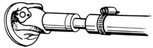
- Unbalanced drivelines can cause vibration that occurs throughout the speed range of vehicle and varies in intensity with a change of speed. The driveline may be at fault in respect to balance and concentricity. A quick field check to determine driveline balance can be made by securing a small piece of metal or similar weight with a hose clamp to the front of the tube where the splined shaft is welded. Road test the vehicle and continue to move the weight around the tube until the balance point is found and vibration disappears or is minimized.
Drivelines are dynamically balanced to their intended rotational velocity and not to infinite speeds. Thus, vibration can be expected when this rotational velocity is exceeded. Check concentricity of driveline by mounting on lathe centers and dial indicating. Check manufacturer’s specifications for runout allowance. - Engine supports that are worn, broken or loose, and mounting pads that are worn or deteriorated must be corrected to restore the engine suspension to its original vibration tolerance.
Taking Readings


Take readings with protractor from machined surfaces of yokes or companion flanges. Plain, wing or flange type joints may be encountered. Some will require partial disassembly to obtain accurate readings.
On plain type joints, it may be necessary to remove the bearing cap. When taking readings, make sure the universal joint is in a vertical plane. At the rear axle, take readings from a machined surface differential carrier that is in the same plane as the axle pinion shaft, or from machined surface that is perpendicular to pinion shaft, whichever is easier.
If vibration occurs while operating empty, take readings in empty condition. If it occurs when loaded, take readings when loaded. When it is necessary to measure driveline lengths, measure from joint center to joint center
Manufacturer’s specifications should be followed when making initial angularity check. Some manufacturers have found it necessary to vary from the ideal due to geometrical limitations. If vibration persists after adhering to manufacturer’s specifications, contact the manufacturer’s representative.
Angularity Checks – Parallel Flanges or Yokes
- Single Axle Vehicles
- Transmission angle – Take reading of transmission angle. This angle is the angle to which the rear axle joint angle must match. The transmission angle will have a declination reading of from 0 to 5 degrees in most cases.
- Axle angle. Take reading either from machined surface of axle housing or pinion bearing retainer. This angle must be within one degree of the transmission angle.
- Example: If transmission angle reading is 3 degrees down to the rear, the rear axle angle should be 3 degrees up.
- Transmission angle – Take reading of transmission angle. This angle is the angle to which the rear axle joint angle must match. The transmission angle will have a declination reading of from 0 to 5 degrees in most cases.
- Tandem Axles or Vehicles with Auxiliary Units
- Take transmission angle reading.
- Take reading from joint of front tandem axle or auxiliary joint. This reading should be within one degree of transmission angle.
- Note: The rear joint of front tandem axle will be the same as the front joint.
- Take reading of joint angle at tandem rear axle, or axle to rear of auxiliary. This angle must be within one degree of transmission angle.
Joint Working Angle Limits (Parallel)
Universal joints have a maximum working angle, depending on type and manufacture. It is recommended that the joint working angle for parallel joint assembly not exceed 8 degrees for main drivelines over 40″ long. For main drivelines under 40″ the maximum angle should not exceed Length (L) divided by 5. (This limit does not apply to interaxle drivelines.)
Example: For a 35″ driveline, the maximum joint working angle would be 35 plus 5 or 7degrees. This working angle must not be exceeded.
Place protractor on driveline to obtain angle of driveline from transmission to axle. The difference between the driveline angle and the joint angle is the joint working angle. For instance, if the transmission is 3 degrees down, and the driveline angle is down 7 degrees, the transmission joint working angle is 7 minus 3 or 4 degrees.
On tandem drive or auxiliary installations, take readings in the same manner, comparing the universal joint angles to the driveline angle to which it is attached.
Angularity Checks – Non-Parallel Compensating Angles or Flanges or Yokes
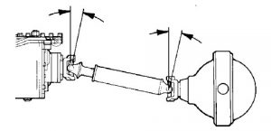
With short wheel base vehicles which have a minimum driveline length from transmission to axle, the driveline is required to operate through very severe working angles on some installations. This also applies to interaxle drivelines. These severe joint working angles induce vibration. To decrease working angles, the axle is tilted upward until the pinion shaft centerline and transmission mainshaft centerline intersect midway between the joint centers.

With tandem drive axles, the rearward axle is tilted upward until its pinion shaft centerline and forward axle pinion shaft centerline intersect midway between joint centers.
When figuring non-parallel joint installations, it is necessary to take the driveline angle readings as well as transmission and axle angle readings.
- Single Axle Vehicles
- Take angle reading of transmission
- Take angle of driveline
- Take angle reading of axle joint
- To compute for correct angles:
- The difference between the driveline angle and the transmission angle will be the transmission joint working angle.
- The difference between the driveline angle and the axle angle will be the axle joint working angle.
- The two working angles of transmission and axle must be equal.
- Example:
Transmission is 3 degrees down
Driveline is 7.5 degrees down
Rear axle is 12 degrees down
Thus 7.5 minus 3 equals 4.5 degrees
12 minus 7.5 equals 4.5 degrees, giving 4.5 equal working angles
- Tandem Axles or Vehicles with Auxiliary Units – When taking readings on tandem drive axles or between auxiliary and rear axle, the same principles apply as with single axle vehicles. Take readings between transmission and front tandem axle, or auxiliary. Take readings between axles or between auxiliary and axle. In other words, take angle readings for each set of universal joints
Joint Working Angle Limits (Non-Parallel)
It is recommended that the maximum joint working angle for non-parallel joint assemblies not exceed the main driveline length divided by 10. For example, if the main driveline length is 55, the maximum joint working angle is 55 divided by 10 or 5.5 degrees. (This limit does not apply to interaxle drivelines.)
Axle Adjustments
Axle angles may generally be adjusted by one of the following ways, depending on the type of axle.
- Adjust torque rods, if adjustable type.
- Add to or reduce length of non-adjustable torque rods.
- Add or reduce the number of shims behind torque rod brackets.
- Use correct amount of wedge shims under spring to axle pad.
Suspensions – Pinion Shaft Angle
There will be little or no change of axle pinion angle with types of suspensions which have a parallelogram movement. These allow differential housings to move up and down in a straight vertical during operation.
Suspensions not having a parallelogram movement will allow axle pinion shaft to oscillate in an arc, thereby constantly changing pinion shaft angle during operation. A varying amount of vibration can occur caused by working angles of the universal joints being momentarily unequal.
Single drive axle vehicles have little or no change of axle pinion angle during operation.

Any transmission part you need we have it! Same day shipping available, worldwide.
NEED FREE SUPPORT FROM ONE OF OUR EXPERTS?