[fusion_builder_container hundred_percent=”no” hundred_percent_height=”no” hundred_percent_height_scroll=”no” hundred_percent_height_center_content=”yes” equal_height_columns=”no” menu_anchor=”” hide_on_mobile=”small-visibility,medium-visibility,large-visibility” status=”published” publish_date=”” class=”” id=”” background_color=”” background_image=”” background_position=”center center” background_repeat=”no-repeat” fade=”no” background_parallax=”none” enable_mobile=”no” parallax_speed=”0.3″ video_mp4=”” video_webm=”” video_ogv=”” video_url=”” video_aspect_ratio=”16:9″ video_loop=”yes” video_mute=”yes” video_preview_image=”” border_size=”” border_color=”” border_style=”solid” margin_top=”35″ margin_bottom=”” padding_top=”” padding_right=”” padding_bottom=”” padding_left=””][fusion_builder_row][fusion_builder_column type=”1_1″ layout=”1_1″ spacing=”” center_content=”no” link=”” target=”_self” min_height=”” hide_on_mobile=”small-visibility,medium-visibility,large-visibility” class=”” id=”” background_color=”” background_image=”” background_image_id=”” background_position=”left top” background_repeat=”no-repeat” hover_type=”none” border_size=”0″ border_color=”” border_style=”solid” border_position=”all” padding_top=”” padding_right=”” padding_bottom=”” padding_left=”” margin_top=”” margin_bottom=”” animation_type=”” animation_direction=”left” animation_speed=”0.3″ animation_offset=”” last=”no”][fusion_text columns=”” column_min_width=”” column_spacing=”” rule_style=”default” rule_size=”” rule_color=”” hide_on_mobile=”small-visibility,medium-visibility,large-visibility” class=”” id=””]
Eaton Fuller Hybrid Transmission Fejlkode 116 – High Voltage Relæer -(MY08 Systems)
[/fusion_text][/fusion_builder_column][/fusion_builder_row][/fusion_builder_container][fusion_builder_container hundred_percent=”no” hundred_percent_height=”no” hundred_percent_height_scroll=”no” hundred_percent_height_center_content=”yes” equal_height_columns=”no” menu_anchor=”” hide_on_mobile=”small-visibility,medium-visibility,large-visibility” status=”published” publish_date=”” class=”” id=”” background_color=”” background_image=”” background_position=”center center” background_repeat=”no-repeat” fade=”no” background_parallax=”none” enable_mobile=”no” parallax_speed=”0.3″ video_mp4=”” video_webm=”” video_ogv=”” video_url=”” video_aspect_ratio=”16:9″ video_loop=”yes” video_mute=”yes” video_preview_image=”” border_size=”” border_color=”” border_style=”solid” margin_top=”” margin_bottom=”” padding_top=”” padding_right=”” padding_bottom=”” padding_left=””][fusion_builder_row][fusion_builder_column type=”1_1″ layout=”1_1″ spacing=”” center_content=”no” link=”” target=”_self” min_height=”” hide_on_mobile=”small-visibility,medium-visibility,large-visibility” class=”” id=”” background_color=”” background_image=”” background_image_id=”” background_position=”left top” background_repeat=”no-repeat” hover_type=”none” border_size=”0″ border_color=”” border_style=”solid” border_position=”all” padding_top=”” padding_right=”” padding_bottom=”” padding_left=”” margin_top=”” margin_bottom=”” animation_type=”” animation_direction=”left” animation_speed=”0.3″ animation_offset=”” last=”no”][fusion_text columns=”” column_min_width=”” column_spacing=”” rule_style=”default” rule_size=”” rule_color=”” hide_on_mobile=”small-visibility,medium-visibility,large-visibility” class=”” id=””]
Fejlkode for Eaton Hybrid Drive Systems modeller (MY08) EH-8E306A-U, EH-8E306A-UPG, EH-8E306A-UP, EH-8E306A-cd, EH-8E306A-T, EH-6E606B-cd. Læs nedenfor for at lære at teste, klare og reparere fejl kode fejl til din Freightliner, Mack, Peterbilt, Kenworth, Volvo, International, og tunge lastbiler og udstyr. The High-Voltage Relays are located inside the Power Electronics Carrier (PEC) i Relæboks enhed. There is 1 precharge relay on the positive side, et ekstra relæ på den positive, og 1 on the negative for a total of 3. Disse relæer er normalt åbne, når systemet er slukket. Relæerne styres gennem inverteren.
fejlkode 116 – High Voltage Relays Detection
Følgende forudsætninger skal være opfyldt, før systemet registrerer fejlen:
- Inverter tænding spænding er større end 7 volts og mindre end 16 volt.
Bemærk: Ved fejlfinding en inaktiv kode henvises til Produkt Diagnostic tilstand (PDM)
Forhold til Set Fejlkode Aktiv
- IMF 10 is set when the Inverter detects the input voltage measured at the capacitor is less than 210 volts within 3 seconds after the sub-relay closed in the Relay Box.
- IMF 14 is set when only the negative relay in the Relay Box is on and capacitor voltage decreases less than 10 volts/5 seconds when initial capacitor voltage was greater than 200 volts and motor speed less than 500 min-1, or there is a detect error in the initial check.
Fallback Når Fejlkode 116 er indstillet følgende sker:
- Amber ”Kontrollér Hybrid” blinker i FMI 10 and remains solid for FMI 14.
- Fejl lagres i HCM hukommelse.
- Inverter lukker højspændingsanlæg off.
- HCM fortsætter med at styre den hybride køretøj i en diesel-tilstand.
- Transmission defaults starte gear til 1st.
[/fusion_text][fusion_text columns=”” column_min_width=”” column_spacing=”” rule_style=”default” rule_size=”” rule_color=”” hide_on_mobile=”small-visibility,medium-visibility,large-visibility” class=”” id=””]
Forhold til Set Fejl kode inaktiv
Kun Inaktive fejl kan ryddes fra Transmission Electronic Control Unit (TECU) eller HCM historik ved hjælp ServiceRanger. Den TECU rydder automatisk de fejl fra historie efter 200 timer og HCM rydder automatisk de fejl fra historien, efter at fejlen har været inaktiv i 200 timer.
Denne fejlkode kan være forårsaget af et af følgende:
- IMF 10
- PEC
- APG
- Inverter
- DC high-voltage cable
- DC cable interlock loops
- inerti switch
- tjeneste Skift
- IMF 14
- Inverter
- PEC
[/fusion_text][/fusion_builder_column][/fusion_builder_row][/fusion_builder_container][fusion_builder_container hundred_percent=”no” hundred_percent_height=”no” hundred_percent_height_scroll=”no” hundred_percent_height_center_content=”yes” equal_height_columns=”no” menu_anchor=”” hide_on_mobile=”small-visibility,medium-visibility,large-visibility” status=”published” publish_date=”” class=”” id=”” background_color=”” background_image=”” background_position=”center center” background_repeat=”no-repeat” fade=”no” background_parallax=”none” enable_mobile=”no” parallax_speed=”0.3″ video_mp4=”” video_webm=”” video_ogv=”” video_url=”” video_aspect_ratio=”16:9″ video_loop=”yes” video_mute=”yes” video_preview_image=”” border_size=”” border_color=”” border_style=”solid” margin_top=”” margin_bottom=”” padding_top=”” padding_right=”” padding_bottom=”” padding_left=””][fusion_builder_row][fusion_builder_column type=”1_1″ layout=”1_1″ spacing=”” center_content=”no” link=”” target=”_self” min_height=”” hide_on_mobile=”small-visibility,medium-visibility,large-visibility” class=”” id=”” background_color=”” background_image=”” background_image_id=”” background_position=”left top” background_repeat=”no-repeat” hover_type=”none” border_size=”0″ border_color=”” border_style=”solid” border_position=”all” padding_top=”” padding_right=”” padding_bottom=”” padding_left=”” margin_top=”” margin_bottom=”” animation_type=”” animation_direction=”left” animation_speed=”0.3″ animation_offset=”” last=”no”][fusion_text columns=”” column_min_width=”” column_spacing=”” rule_style=”default” rule_size=”” rule_color=”” hide_on_mobile=”small-visibility,medium-visibility,large-visibility” class=”” id=””]
fejlkode 116 – High Voltage Relays Test
[/fusion_text][/fusion_builder_column][/fusion_builder_row][/fusion_builder_container][fusion_builder_container hundred_percent=”no” hundred_percent_height=”no” hundred_percent_height_scroll=”no” hundred_percent_height_center_content=”yes” equal_height_columns=”no” menu_anchor=”” hide_on_mobile=”small-visibility,medium-visibility,large-visibility” status=”published” publish_date=”” class=”” id=”” background_color=”” background_image=”” background_position=”center center” background_repeat=”no-repeat” fade=”no” background_parallax=”none” enable_mobile=”no” parallax_speed=”0.3″ video_mp4=”” video_webm=”” video_ogv=”” video_url=”” video_aspect_ratio=”16:9″ video_loop=”yes” video_mute=”yes” video_preview_image=”” border_size=”” border_color=”” border_style=”solid” margin_top=”” margin_bottom=”” padding_top=”” padding_right=”” padding_bottom=”” padding_left=””][fusion_builder_row][fusion_builder_column type=”1_1″ layout=”1_1″ spacing=”” center_content=”no” link=”” target=”_self” min_height=”” hide_on_mobile=”small-visibility,medium-visibility,large-visibility” class=”” id=”” background_color=”” background_image=”” background_image_id=”” background_position=”left top” background_repeat=”no-repeat” hover_type=”none” border_size=”0″ border_color=”” border_style=”solid” border_position=”all” padding_top=”” padding_right=”” padding_bottom=”” padding_left=”” margin_top=”” margin_bottom=”” animation_type=”” animation_direction=”left” animation_speed=”0.3″ animation_offset=”” last=”no”][fusion_text columns=”” column_min_width=”” column_spacing=”” rule_style=”default” rule_size=”” rule_color=”” hide_on_mobile=”small-visibility,medium-visibility,large-visibility” class=”” id=””]
Component Identifikation MY08 Systems:
[/fusion_text][/fusion_builder_column][/fusion_builder_row][/fusion_builder_container][fusion_builder_container hundred_percent=”yes” hundred_percent_height=”no” hundred_percent_height_scroll=”no” hundred_percent_height_center_content=”yes” equal_height_columns=”no” menu_anchor=”” hide_on_mobile=”small-visibility,medium-visibility,large-visibility” status=”published” publish_date=”” class=”” id=”” background_color=”” background_image=”” background_position=”center center” background_repeat=”no-repeat” fade=”no” background_parallax=”none” enable_mobile=”no” parallax_speed=”0.3″ video_mp4=”” video_webm=”” video_ogv=”” video_url=”” video_aspect_ratio=”16:9″ video_loop=”yes” video_mute=”yes” video_preview_image=”” border_size=”” border_color=”” border_style=”solid” margin_top=”” margin_bottom=”” padding_top=”” padding_right=”10%” padding_bottom=”” padding_left=”10%”][fusion_builder_row][fusion_builder_column type=”1_3″ layout=”1_3″ spacing=”” center_content=”no” link=”” target=”_self” min_height=”” hide_on_mobile=”small-visibility,medium-visibility,large-visibility” class=”” id=”” background_color=”” background_image=”” background_image_id=”” background_position=”left top” background_repeat=”no-repeat” hover_type=”none” border_size=”0″ border_color=”” border_style=”solid” border_position=”all” padding_top=”” padding_right=”” padding_bottom=”” padding_left=”” margin_top=”” margin_bottom=”” animation_type=”” animation_direction=”left” animation_speed=”0.3″ animation_offset=”” last=”no”][fusion_imageframe image_id=”14474|full” max_width=”” style_type=”” blur=”” stylecolor=”” hover_type=”none” bordersize=”” bordercolor=”” borderradius=”” align=”center” lightbox=”no” gallery_id=”” lightbox_image=”” lightbox_image_id=”” alt=”Delphi 56-vejs Parring Connector Se” link=”” linktarget=”_self” hide_on_mobile=”small-visibility,medium-visibility,large-visibility” class=”” id=”” animation_type=”” animation_direction=”left” animation_speed=”0.3″ animation_offset=””]https://www.globaltransmissionsupply.com/wp-content/uploads/Inverter-56-Way-Mating-Connector-View.jpg[/fusion_imageframe][fusion_text columns=”” column_min_width=”” column_spacing=”” rule_style=”default” rule_size=”” rule_color=”” hide_on_mobile=”small-visibility,medium-visibility,large-visibility” class=”” id=””]
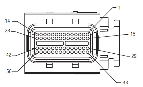
56-Way Parring Connector Se
[/fusion_text][/fusion_builder_column][fusion_builder_column type=”1_3″ layout=”1_3″ spacing=”” center_content=”no” link=”” target=”_self” min_height=”” hide_on_mobile=”small-visibility,medium-visibility,large-visibility” class=”” id=”” background_color=”” background_image=”” background_image_id=”” background_position=”left top” background_repeat=”no-repeat” hover_type=”none” border_size=”0″ border_color=”” border_style=”solid” border_position=”all” padding_top=”” padding_right=”” padding_bottom=”” padding_left=”” margin_top=”” margin_bottom=”” animation_type=”” animation_direction=”left” animation_speed=”0.3″ animation_offset=”” last=”no”][fusion_imageframe image_id=”14635|full” max_width=”” style_type=”” blur=”” stylecolor=”” hover_type=”none” bordersize=”” bordercolor=”” borderradius=”” align=”center” lightbox=”no” gallery_id=”” lightbox_image=”” lightbox_image_id=”” alt=”High Voltage DC Connector Se Yazaki Connector” link=”” linktarget=”_self” hide_on_mobile=”small-visibility,medium-visibility,large-visibility” class=”” id=”” animation_type=”” animation_direction=”left” animation_speed=”0.3″ animation_offset=””]https://www.globaltransmissionsupply.com/wp-content/uploads/High-Voltage-DC-Connector-View.jpg[/fusion_imageframe][fusion_text columns=”” column_min_width=”” column_spacing=”” rule_style=”default” rule_size=”” rule_color=”” hide_on_mobile=”small-visibility,medium-visibility,large-visibility” class=”” id=””]
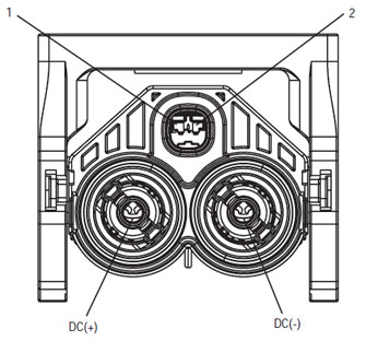
High Voltage DC Connector Se Yazaki Connector
[/fusion_text][/fusion_builder_column][fusion_builder_column type=”1_3″ layout=”1_3″ spacing=”” center_content=”no” link=”” target=”_self” min_height=”” hide_on_mobile=”small-visibility,medium-visibility,large-visibility” class=”” id=”” background_color=”” background_image=”” background_image_id=”” background_position=”left top” background_repeat=”no-repeat” hover_type=”none” border_size=”0″ border_color=”” border_style=”solid” border_position=”all” padding_top=”” padding_right=”” padding_bottom=”” padding_left=”” margin_top=”” margin_bottom=”” animation_type=”” animation_direction=”left” animation_speed=”0.3″ animation_offset=”” last=”no”][fusion_imageframe image_id=”14213|medium” max_width=”” style_type=”” blur=”” stylecolor=”” hover_type=”none” bordersize=”” bordercolor=”” borderradius=”” align=”center” lightbox=”no” gallery_id=”” lightbox_image=”” lightbox_image_id=”” alt=”Mating Connector View Deutsch 19 – Vej” link=”” linktarget=”_self” hide_on_mobile=”small-visibility,medium-visibility,large-visibility” class=”” id=”” animation_type=”” animation_direction=”left” animation_speed=”0.3″ animation_offset=””]https://www.globaltransmissionsupply.com/wp-content/uploads/Eaton-Fuller-Harness-Connector-View-300×289.jpg[/fusion_imageframe][fusion_text columns=”” column_min_width=”” column_spacing=”” rule_style=”default” rule_size=”” rule_color=”” hide_on_mobile=”small-visibility,medium-visibility,large-visibility” class=”” id=””]
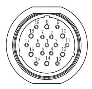
Mating Connector View Deutsch 19 – Vej
[/fusion_text][/fusion_builder_column][/fusion_builder_row][/fusion_builder_container][fusion_builder_container hundred_percent=”no” hundred_percent_height=”no” hundred_percent_height_scroll=”no” hundred_percent_height_center_content=”yes” equal_height_columns=”no” menu_anchor=”” hide_on_mobile=”small-visibility,medium-visibility,large-visibility” status=”published” publish_date=”” class=”” id=”” background_color=”” background_image=”” background_position=”center center” background_repeat=”no-repeat” fade=”no” background_parallax=”none” enable_mobile=”no” parallax_speed=”0.3″ video_mp4=”” video_webm=”” video_ogv=”” video_url=”” video_aspect_ratio=”16:9″ video_loop=”yes” video_mute=”yes” video_preview_image=”” border_size=”” border_color=”” border_style=”solid” margin_top=”” margin_bottom=”” padding_top=”” padding_right=”” padding_bottom=”” padding_left=””][fusion_builder_row][fusion_builder_column type=”1_1″ layout=”1_1″ spacing=”” center_content=”no” link=”” target=”_self” min_height=”” hide_on_mobile=”small-visibility,medium-visibility,large-visibility” class=”” id=”” background_image_id=”” background_color=”#000000″ background_image=”” background_position=”left top” undefined=”” background_repeat=”no-repeat” hover_type=”none” border_size=”0″ border_color=”” border_style=”solid” border_position=”all” padding_top=”” padding_right=”” padding_bottom=”” padding_left=”” margin_top=”” margin_bottom=”” animation_type=”” animation_direction=”left” animation_speed=”0.3″ animation_offset=”” last=”no”][fusion_text columns=”” column_min_width=”” column_spacing=”” rule_style=”default” rule_size=”” rule_color=”” hide_on_mobile=”small-visibility,medium-visibility,large-visibility” class=”” id=””]
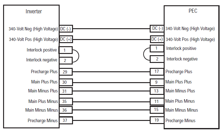
BEMÆRK: Der henvises til Eaton Hybrid Component og Connector Beliggenhed til Connector Steder i MY08 Systems
[/fusion_text][/fusion_builder_column][fusion_builder_column type=”1_1″ layout=”1_1″ spacing=”” center_content=”no” link=”” target=”_self” min_height=”” hide_on_mobile=”small-visibility,medium-visibility,large-visibility” class=”” id=”” background_color=”” background_image=”” background_image_id=”” background_position=”left top” background_repeat=”no-repeat” hover_type=”none” border_size=”0″ border_color=”” border_style=”solid” border_position=”all” padding_top=”” padding_right=”” padding_bottom=”” padding_left=”” margin_top=”” margin_bottom=”” animation_type=”” animation_direction=”left” animation_speed=”0.3″ animation_offset=”” last=”no”][fusion_imageframe image_id=”14666|full” max_width=”” style_type=”” blur=”” stylecolor=”” hover_type=”none” bordersize=”” bordercolor=”” borderradius=”” align=”center” lightbox=”no” gallery_id=”” lightbox_image=”” lightbox_image_id=”” alt=”Inverter PEC connectors Eaton Fuller Hybrid transmission” link=”” linktarget=”_self” hide_on_mobile=”small-visibility,medium-visibility,large-visibility” class=”” id=”” animation_type=”” animation_direction=”left” animation_speed=”0.3″ animation_offset=””]https://www.globaltransmissionsupply.com/wp-content/uploads/Inverter-PEC-connectors.png[/fusion_imageframe][/fusion_builder_column][/fusion_builder_row][/fusion_builder_container][fusion_builder_container hundred_percent=”no” hundred_percent_height=”no” hundred_percent_height_scroll=”no” hundred_percent_height_center_content=”yes” equal_height_columns=”no” menu_anchor=”” hide_on_mobile=”small-visibility,medium-visibility,large-visibility” status=”published” publish_date=”” class=”” id=”” background_color=”” background_image=”” background_position=”center center” background_repeat=”no-repeat” fade=”no” background_parallax=”none” enable_mobile=”no” parallax_speed=”0.3″ video_mp4=”” video_webm=”” video_ogv=”” video_url=”” video_aspect_ratio=”16:9″ video_loop=”yes” video_mute=”yes” video_preview_image=”” border_size=”” border_color=”” border_style=”solid” margin_top=”” margin_bottom=”” padding_top=”” padding_right=”” padding_bottom=”” padding_left=””][fusion_builder_row][fusion_builder_column type=”1_1″ layout=”1_1″ spacing=”” center_content=”no” link=”” target=”_self” min_height=”” hide_on_mobile=”small-visibility,medium-visibility,large-visibility” class=”” id=”” background_color=”” background_image=”” background_image_id=”” background_position=”left top” background_repeat=”no-repeat” hover_type=”none” border_size=”0″ border_color=”” border_style=”solid” border_position=”all” padding_top=”” padding_right=”” padding_bottom=”” padding_left=”” margin_top=”” margin_bottom=”” animation_type=”” animation_direction=”left” animation_speed=”0.3″ animation_offset=”” last=”no”][fusion_modal name=”warnings_cautions” title=”Advarsler & Forsigtig” size=”large” background=”” border_color=”” show_footer=”yes” class=”” id=””]Fare: Fare angiver, at du vil blive alvorligt såret eller dræbt, hvis ikke følger den angivne procedure.
Advarsel: Advarsel angiver en umiddelbar fare, hvilket kan resultere i alvorlig personskade, hvis du ikke følger den angivne procedure.
Advarsel: Forsigtig angiver køretøj eller materiel skade kunne opstå, hvis du ikke følger den angivne procedure.
Bemærk: Bemærk indikerer yderligere detaljer, der vil hjælpe i diagnosticering eller reparation af en komponent / system.
Følg de angivne procedurer i den angivne rækkefølge for at undgå personskade:
1. Hvis højspændingsledninger kegler er omkring køretøjet og lockout er installeret på PEC, den eneste person, der skal have lov til at starte køretøjet er den person, der har underskrevet lockout tag.
2. Før der arbejdes på et køretøj eller forlade kabinen, mens motoren kører, du skal placere gearvælgeren i ”N” træk parkeringsbremsen, og blokere hjulene.
3. Af sikkerhedsmæssige årsager, altid i indgreb driftsbremserne forud for valg gearstillinger fra ”N.”
4. Før du starter et køretøj altid blive siddende i førersædet, Vælg ”N” på skift kontrol, og indstille parkeringsbremser.
5. I biler med ePTO, motoren og / eller
Motor / generator kan starte i ePTO tilstand. Aldrig udføre nogen form for vedligeholdelse eller arbejde på køretøj, mens i denne tilstand.
6. 12-Volt Batteri positiv (+) og negativ (-) skal frakobles forud for enhver svejsning på enhver Hybrid udstyrede køretøjs.
Advarsel: Følg de angivne procedurer i den angivne rækkefølge for at undgå fejlfunktion eller beskadigelse.
Advarsel: Slip ikke parkeringsbremsen eller forsøge at vælge et gear, indtil lufttrykket er på det korrekte niveau.
Advarsel: For at undgå beskadigelse af transmissionen under bugsering sted gearstangen i ”N” og løft drivhjulene fra jorden eller afbryde drivlinen.
Højspændingsledninger Advarsler & Forsigtig
- Brug af CO2 eller pulver Brandslukkere.
- Højspændingen ledninger er dækket i orange isolering eller indviklede slanger og mærket med advarselsskilte på stikkene.
- Alle Eaton® Hybrid Diesel / Elektriske køretøjer vil blive markeret ’Hybrid’ på ydersiden af køretøjet, sammen med skiftet etiket på instrumentbrættet.
- Der henvises til OEM for specifikke placering af chassis monteret hybride komponenter.
- Må ikke skåret i de orange højspændingskabler.
- Må ikke skåret i eller åbne PEC.
- Må ikke skåret i eller åbn DC / DC-konverter.
- Må ikke skåret i eller åbn inverter.
En buffer zone skal oprettes og højspænding isolerede gummihandsker (klasse 0 med læder beskyttere) er påkrævet før arbejder på højspænding. Manglende overholdelse af disse instruktioner kan medføre alvorlig personskade eller død.
Gummi-isolerede handsker, der skal bæres under arbejdet på Højspændingsnettet er klasse 0 med læder beskyttere. De gummihandsker bør testes før hver brug følge proceduren gummi isolering handsker test findes i ”Diagnostiske Tools / Tjenesteydelser Publikationer” på side 6. Manglende overholdelse af disse instruktioner kan medføre alvorlig personskade eller død.
Før inspektion eller arbejder på eventuelle højspændingskabler eller komponenter ”High-Voltage service Nedlukning og Power-Up fremgangsmåde” på side 4 bør følges. Manglende overholdelse af disse instruktioner kan medføre alvorlig personskade eller død.
Lockout og Tagout enheder bør kun fjernes af teknikeren, der er tilføjet de Lockout og Tagout enheder på køretøjet. Manglende overholdelse af disse instruktioner kan medføre alvorlig personskade eller død.
Højspændingsledninger gummi isolerede handsker (klasse 0 med læder beskyttere) skal bæres, når der arbejdes på en hvilken som helst
højspændingsledninger. Den ”High-Voltage service Nedlukning og Power-Up fremgangsmåde” på side 4 skal følges før fjernelse af eventuelle højspændingsledninger. Manglende overholdelse af disse instruktioner kan medføre alvorlig personskade eller død.
Højspændingsledninger kabler og ledninger er orange og indeholde en advarsel på stikkene. Højspændingsdele er markeret med en etiket. Højspændingsledninger gummi isolerede handsker (klasse 0 med læder beskyttere) skal anvendes ved arbejde på enhver af disse komponenter. Manglende overholdelse af disse instruktioner kan medføre alvorlig personskade eller død.
Højspændingsledninger service Shutdown Procedurer

1. Følg ”High-Voltage Arbejdsområdet” procedure.
2. Find den røde PEC service Tænd forsiden af PEC og skub slukker.
3. Fjern Tjenesten Skift Cover og installere Lockout Bracket (J48506).
4. Fastgør tag til Lockout Bracket.
5. Sørg for PEC service switch kan ikke bevæge sig fra den slukket position.
6. Lad systemet til at sætte i mindst 5 minutter for at aflade højspænding.
7. Slut ServiceRanger og se data Monitor PID 116 kaldet ”High-Voltage Batteri Potential.” Brug SPN 520323 til J1939 forbindelse ”Batterispænding RB” (Relæ Box).
8. Spændingen skal være 30 volts eller mindre. Hvis spændingen er over 30 volt, virker ikke på køretøjet og kontakte Eaton® på 1-800-826-HELP (4357).
9. Drej tændingsnøglen ud og gå videre til at reparere eller fejlfinding.
Bemærk: Spændingen falder til nul, når nøglen er slukket.
High-Voltage service Power-Up Procedure
1. Installere alle højspænding stik i deres låste positioner.
2. Hvis du er den person, der arbejder på køretøjet, fjerne Lockout beslag og tag.
3. Geninstaller Lockout Bracket over service switch.
4. Træk Tjenesten Omlæg og lad bilen sæt til 2 minutter.
5. Start vehicle when appropriate.[/fusion_modal][fusion_modal name=”component_location” title=”Eaton Hybrid Component og Connector Beliggenhed ” size=”large” background=”#ffffff” border_color=”” show_footer=”yes” class=”” id=””]

[/fusion_modal][fusion_modal name=”component_location2″ title=”Eaton Hybrid Component og Connector Beliggenhed MY09 Systems” size=”large” background=”#ffffff” border_color=”” show_footer=”yes” class=”” id=””]

[/fusion_modal][/fusion_builder_column][/fusion_builder_row][/fusion_builder_container][fusion_builder_container hundred_percent=”no” hundred_percent_height=”no” hundred_percent_height_scroll=”no” hundred_percent_height_center_content=”yes” equal_height_columns=”no” menu_anchor=”” hide_on_mobile=”small-visibility,medium-visibility,large-visibility” status=”published” publish_date=”” class=”” id=”” background_color=”” background_image=”” background_position=”center center” background_repeat=”no-repeat” fade=”no” background_parallax=”none” enable_mobile=”no” parallax_speed=”0.3″ video_mp4=”” video_webm=”” video_ogv=”” video_url=”” video_aspect_ratio=”16:9″ video_loop=”yes” video_mute=”yes” video_preview_image=”” border_size=”” border_color=”” border_style=”solid” margin_top=”” margin_bottom=”” padding_top=”” padding_right=”” padding_bottom=”” padding_left=””][fusion_builder_row][fusion_builder_column type=”1_1″ layout=”1_1″ spacing=”” center_content=”no” link=”” target=”_self” min_height=”” hide_on_mobile=”small-visibility,medium-visibility,large-visibility” class=”” id=”” background_color=”” background_image=”” background_image_id=”” background_position=”left top” background_repeat=”no-repeat” hover_type=”none” border_size=”0″ border_color=”” border_style=”solid” border_position=”all” padding_top=”” padding_right=”” padding_bottom=”” padding_left=”” margin_top=”” margin_bottom=”” animation_type=”” animation_direction=”left” animation_speed=”0.3″ animation_offset=”” last=”no”][fusion_content_boxes layout=”clean-horizontal” columns=”2″ title_size=”18px” heading_size=”3″ title_color=”#ffffff” body_color=”#ffffff” backgroundcolor=”#4f4f4f” icon=”” iconflip=”” iconrotate=”” iconspin=”no” iconcolor=”” icon_circle=”” icon_circle_radius=”” circlecolor=”” circlebordersize=”” circlebordercolor=”” outercirclebordersize=”” outercirclebordercolor=”” icon_size=”” icon_hover_type=”” hover_accent_color=”” image=”” image_id=”” image_width=”” image_height=”” link_type=”” button_span=”” link_area=”” link_target=”” icon_align=”left” animation_type=”” animation_delay=”” animation_offset=”” animation_direction=”left” animation_speed=”0.3″ margin_top=”” margin_bottom=”” hide_on_mobile=”small-visibility,medium-visibility,large-visibility” class=”” id=””][fusion_content_box title=”TRIN 1. Verificere FMIs foreliggende.” backgroundcolor=”” icon=”” iconflip=”” iconrotate=”” iconspin=”no” iconcolor=”” circlecolor=”” circlebordersize=”” circlebordercolor=”” outercirclebordersize=”” outercirclebordercolor=”” image=”” image_id=”” image_width=”” image_height=”” link=”” linktext=”Læs mere” link_target=”” animation_type=”” animation_direction=”left” animation_speed=”0.3″ animation_offset=””]
- Gennemgå og følg Advarsler & Forsigtig.
- Hent Aktive fejlkoder og FMIs med ServiceRanger ved hjælp af 9-vejs Diagnostic Connector.
Fare: Se High-Voltage service Nedlukning og power-up procedurer. Følg procedurerne for at undgå chok, brænde eller død fra forkert håndteret højspænding. - Hvilke FMIs er til stede
- Hvis Fejlkode 116 IMF 14 er noteret, gå til trin 9.
- Hvis Fejlkode 116 IMF 10 er noteret, gå til trin 2.
- If no Fault Codes are listed, The Service Switch was pushed in. Gå til trin 10.
[/fusion_content_box][fusion_content_box title=”TRIN 2. Verify Data Monitor parameters.” backgroundcolor=”” icon=”” iconflip=”” iconrotate=”” iconspin=”no” iconcolor=”” circlecolor=”” circlebordersize=”” circlebordercolor=”” outercirclebordersize=”” outercirclebordercolor=”” image=”” image_id=”” image_width=”” image_height=”” link=”” linktext=”Læs mere” link_target=”” animation_type=”” animation_direction=”left” animation_speed=”0.3″ animation_offset=””]
- nøgle på.
- Slut ServiceRanger til 9-vejs Diagnostic Connector i førerhuset.
- Vælg ”Data Monitor” valgmulighed.
- View the Battery Pack Voltage (BCU1) PID 118 in the high- voltage Battery list:
- If the Battery Pack Voltage (BCU1) PID 118 is greater than 200 volt, gå til trin 3.
- If the Battery Pack Voltage (BCU1) PID 118 er mindre end 200 volt, erstatte Power Electronics Carrier (PEC), derefter gå til trin 10.
[/fusion_content_box][/fusion_content_boxes][fusion_content_boxes layout=”clean-horizontal” columns=”2″ title_size=”18px” heading_size=”3″ title_color=”#ffffff” body_color=”#ffffff” backgroundcolor=”#4f4f4f” icon=”” iconflip=”” iconrotate=”” iconspin=”no” iconcolor=”” icon_circle=”” icon_circle_radius=”” circlecolor=”” circlebordersize=”” circlebordercolor=”” outercirclebordersize=”” outercirclebordercolor=”” icon_size=”” icon_hover_type=”” hover_accent_color=”” image=”” image_id=”” image_width=”” image_height=”” link_type=”” button_span=”” link_area=”” link_target=”” icon_align=”left” animation_type=”” animation_delay=”” animation_offset=”” animation_direction=”left” animation_speed=”0.3″ margin_top=”” margin_bottom=”” hide_on_mobile=”small-visibility,medium-visibility,large-visibility” class=”” id=””][fusion_content_box title=”TRIN 3. Verify continuity of Inverter connector circuits.” backgroundcolor=”” icon=”” iconflip=”” iconrotate=”” iconspin=”no” iconcolor=”” circlecolor=”” circlebordersize=”” circlebordercolor=”” outercirclebordersize=”” outercirclebordercolor=”” image=”” image_id=”” image_width=”” image_height=”” link=”” linktext=”Læs mere” link_target=”” animation_type=”” animation_direction=”left” animation_speed=”0.3″ animation_offset=””]
- nøgle slukket.
- If the vehicle is not equipped with a DC/DC Converter or APG, skip this step.
- Using ASTM Class 0 electrical insulating rubber gloves with leather protectors, disconnect the DC cable for the DC/DC Converter and APG at the PEC.
- With the key off, temporarily remove the Lockout Bracket and pull the Service Switch out.
- nøgle på.
- Er Fejlkode 116 IMF 10 still Active in ServiceRanger?
- Hvis Fejlkode 116 IMF 10 is Active with the DC/DC Converter and APG disconnected, gå til trin 4.
- Hvis Fejlkode 116 IMF 10 is no longer Active with the DC/DC Converter and APG disconnected, key off and reinstall the Lockout Bracket on the PEC. Replace the Power Electronics Carrier (PEC), derefter gå til trin 10.
[/fusion_content_box][fusion_content_box title=”TRIN 4. Verify continuity of PEC connector circuits to ground.” backgroundcolor=”” icon=”” iconflip=”” iconrotate=”” iconspin=”” iconcolor=”” circlecolor=”” circlebordersize=”” circlebordercolor=”” outercirclebordersize=”” outercirclebordercolor=”” image=”” image_id=”” image_width=”” image_height=”” link=”” linktext=”” link_target=”” animation_type=”” animation_direction=”left” animation_speed=”0.3″ animation_offset=””]
- nøgle slukket.
- Afbryd PEC 19-vejs stik.
- Temporarily remove the Lockout Bracket and pull the Service Switch out.
Bemærk: Ensure the Key Switch is off. - Measure resistance at the PEC 19-Way Connector Terminal at the following pins:
- Pin 17 at sætte fast 19
- Pin 9 at sætte fast 11
- Pin 13 at sætte fast 15
- If the resistance between Pins 17 og Pin 19 er 112-122 ohm og modstanden fra Pin 9 at sætte fast 11 og Pin 13 at sætte fast 15 er hver 33-37 ohm, gå til trin 5.
- Hvis modstanden er uden for rækkevidde, gå til trin 6.
[/fusion_content_box][/fusion_content_boxes][fusion_content_boxes layout=”clean-horizontal” columns=”2″ title_size=”18px” heading_size=”3″ title_color=”#ffffff” body_color=”#ffffff” backgroundcolor=”#4f4f4f” icon=”” iconflip=”” iconrotate=”” iconspin=”no” iconcolor=”” icon_circle=”” icon_circle_radius=”” circlecolor=”” circlebordersize=”” circlebordercolor=”” outercirclebordersize=”” outercirclebordercolor=”” icon_size=”” icon_hover_type=”” hover_accent_color=”” image=”” image_id=”” image_width=”” image_height=”” link_type=”” button_span=”” link_area=”” link_target=”” icon_align=”left” animation_type=”” animation_delay=”” animation_offset=”” animation_direction=”left” animation_speed=”0.3″ margin_top=”” margin_bottom=”” hide_on_mobile=”small-visibility,medium-visibility,large-visibility” class=”” id=””][fusion_content_box title=”TRIN 5. Verify continuity of Inverter connector circuits to ground.” backgroundcolor=”” icon=”” iconflip=”” iconrotate=”” iconspin=”no” iconcolor=”” circlecolor=”” circlebordersize=”” circlebordercolor=”” outercirclebordersize=”” outercirclebordercolor=”” image=”” image_id=”” image_width=”” image_height=”” link=”” linktext=”Læs mere” link_target=”” animation_type=”” animation_direction=”left” animation_speed=”0.3″ animation_offset=””]
- nøgle slukket.
- Reconnect the PEC 19-Way Connector.
- Afbryd inverteren 56-Way Connector.
- Inspect the connector pins for damaged, corroded and/or loose wires.
- Measure resistance between the Inverter 56-Way Connector at the following pins:
- Pin 29 at sætte fast 37
- Pin 30 at sætte fast 35
- Pin 31 at sætte fast 36 Bemærk: flex forsigtigt inverteren 56-vejs stik udnytte nær Connector under overvågning modstandsværdierne.
- Hvis modstanden mellem Pin 29 og Pin 37 er 112-122 ohm og modstanden fra Pin 30 at sætte fast 35 og Pin 31 at sætte fast 36 er hver 33-37 ohm, push the Service Switch on the PEC and reinstall the Lockout Bracket. Gå til trin 8.
- Hvis modstanden er uden for rækkevidde, repair the Hybrid Harness between the PEC and Inverter, derefter gå til trin 10.
[/fusion_content_box][fusion_content_box title=”TRIN 6. Verify continuity of PEC connector circuits.” backgroundcolor=”” icon=”” iconflip=”” iconrotate=”” iconspin=”” iconcolor=”” circlecolor=”” circlebordersize=”” circlebordercolor=”” outercirclebordersize=”” outercirclebordercolor=”” image=”” image_id=”” image_width=”” image_height=”” link=”” linktext=”” link_target=”” animation_type=”” animation_direction=”left” animation_speed=”0.3″ animation_offset=””]
- nøgle slukket.
- Remove the Air Filter Cover and Air Filter from the PEC. Refer to TRSM1000 for procedures.*
- An Inertia Switch is located at the front of the PEC inside the box and viewable when the Air Filter is removed.
- Using ASTM Class 0 electrical insulating rubber gloves with leather protectors, press the button on the top of the Inertia Switch until heard or felt a click. This switch must be depressed a set distance to reset the switch.
- Measure resistance at the PEC 19-Way Connector Terminal at the following pins:
- Pin 17 at sætte fast 19
- Pin 9 at sætte fast 11
- Pin 13 at sætte fast 15
- qIf the resistance between Pin 17 og Pin 19 er 112-122 ohm og modstanden fra Pin 9 at sætte fast 11 og Pin 13 at sætte fast 15 er hver 33-37 ohm, the Inertia Switch was tripped. Test is complete. Gå til trin 10.
- Hvis modstanden er uden for rækkevidde, push in the Service Switch on the PEC and reinstall the Lockout Bracket, derefter gå til trin 7.
[/fusion_content_box][/fusion_content_boxes][fusion_content_boxes layout=”clean-horizontal” columns=”2″ title_size=”18px” heading_size=”3″ title_color=”#ffffff” body_color=”#ffffff” backgroundcolor=”#4f4f4f” icon=”” iconflip=”” iconrotate=”” iconspin=”no” iconcolor=”” icon_circle=”” icon_circle_radius=”” circlecolor=”” circlebordersize=”” circlebordercolor=”” outercirclebordersize=”” outercirclebordercolor=”” icon_size=”” icon_hover_type=”” hover_accent_color=”” image=”” image_id=”” image_width=”” image_height=”” link_type=”” button_span=”” link_area=”” link_target=”” icon_align=”left” animation_type=”” animation_delay=”” animation_offset=”” animation_direction=”left” animation_speed=”0.3″ margin_top=”” margin_bottom=”” hide_on_mobile=”small-visibility,medium-visibility,large-visibility” class=”” id=””][fusion_content_box title=”TRIN 7. Verify continuity of Inverter connector circuits.” backgroundcolor=”” icon=”” iconflip=”” iconrotate=”” iconspin=”no” iconcolor=”” circlecolor=”” circlebordersize=”” circlebordercolor=”” outercirclebordersize=”” outercirclebordercolor=”” image=”” image_id=”” image_width=”” image_height=”” link=”” linktext=”Læs mere” link_target=”” animation_type=”” animation_direction=”left” animation_speed=”0.3″ animation_offset=””]
- nøgle slukket.
- Disconnect the DC High-Voltage Cable at the PEC Bulkhead and at the Inverter Bulkhead.
- Measure resistance between the Low-Voltage Interlock Pins on the PEC side of the DC High-Voltage Cable:
Bemærk: The Interlock Pins are the two small spade terminals located in the same opening.- If the resistance is 0–0.3 ohms between the Interlock Loop Pins, erstatte Power Electronics Carrier (PEC), derefter gå til trin 10.
- Hvis modstanden er uden for rækkevidde, erstatte DC højspænding kabel, derefter gå til trin 10.
[/fusion_content_box][fusion_content_box title=”TRIN 8. Verify continuity of DC Cable from PEC to Inverter Connector circuits.” backgroundcolor=”” icon=”” iconflip=”” iconrotate=”” iconspin=”” iconcolor=”” circlecolor=”” circlebordersize=”” circlebordercolor=”” outercirclebordersize=”” outercirclebordercolor=”” image=”” image_id=”” image_width=”” image_height=”” link=”” linktext=”” link_target=”” animation_type=”” animation_direction=”left” animation_speed=”0.3″ animation_offset=””]
- nøgle slukket.
- Disconnect the DC High-Voltage Cable at the PEC Bulkhead and the Inverter Bulkhead.
- Measure the resistance of each high-voltage circuit on the cable:
- If the resistance of each high-voltage circuit in the cable is 1 ohm eller mindre, erstatte Inverter, derefter gå til trin 10.
- Hvis modstanden er uden for rækkevidde, replace the DC High-Voltage Cable, derefter gå til trin 10.
[/fusion_content_box][/fusion_content_boxes][fusion_content_boxes layout=”clean-horizontal” columns=”2″ title_size=”18px” heading_size=”3″ title_color=”#ffffff” body_color=”#ffffff” backgroundcolor=”#4f4f4f” icon=”” iconflip=”” iconrotate=”” iconspin=”no” iconcolor=”” icon_circle=”” icon_circle_radius=”” circlecolor=”” circlebordersize=”” circlebordercolor=”” outercirclebordersize=”” outercirclebordercolor=”” icon_size=”” icon_hover_type=”” hover_accent_color=”#f41000″ image=”” image_id=”” image_width=”” image_height=”” link_type=”” button_span=”” link_area=”” link_target=”” icon_align=”left” animation_type=”” animation_delay=”” animation_offset=”” animation_direction=”left” animation_speed=”0.3″ margin_top=”” margin_bottom=”” hide_on_mobile=”small-visibility,medium-visibility,large-visibility” class=”” id=””][fusion_content_box title=”TRIN 9. Verify Data Monitor parameters.” backgroundcolor=”” icon=”” iconflip=”” iconrotate=”” iconspin=”” iconcolor=”” circlecolor=”” circlebordersize=”” circlebordercolor=”” outercirclebordersize=”” outercirclebordercolor=”” image=”” image_id=”” image_width=”” image_height=”” link=”” linktext=”” link_target=”” animation_type=”” animation_direction=”left” animation_speed=”0.3″ animation_offset=””]
- Slut ServiceRanger til 9-vejs Diagnostic Connector i førerhuset.
- Vælg ”Data Monitor” valgmulighed.
- View the following parameters in the High-Voltage Battery list.
- Battery Pack Voltage (BCU1) PID 118
- Battery Voltage PID 116
- If the voltage readings on PID 116 og PID 118 are within 10 volt af hinanden, erstatte Power Electronics Carrier (PEC), derefter gå til trin 10.
- If the voltage readings on PID 116 og PID 118 are greater than 10 volt af hinanden, erstatte Inverter, derefter gå til trin 10.
[/fusion_content_box][fusion_content_box title=”TRIN 10. Bekræft reparation.” backgroundcolor=”” icon=”” iconflip=”” iconrotate=”” iconspin=”no” iconcolor=”” circlecolor=”” circlebordersize=”” circlebordercolor=”” outercirclebordersize=”” outercirclebordercolor=”” image=”” image_id=”” image_width=”” image_height=”” link=”” linktext=”Læs mere” link_target=”” animation_type=”” animation_direction=”left” animation_speed=”0.3″ animation_offset=””]
- nøgle slukket.
- Tilslut alle stik og den negative batterikabel.
- nøgle på.
- klare koder, se Klare Inaktive fejl.
- Kør bilen og forsøger at nulstille koden.
- Kontroller for koder, se Se aktive og inaktive Fejl.
- Hvis der ikke koder, testen er færdig.
- Hvis Fejlkode 116 kommer til syne, kontakt Eaton på 1- 800-826-HJÆLP (4357). Repeat this Step (Trin 10).
- Hvis en kode andet end 116 kommer til syne, se Fejl Kode Indeks Liste.
[/fusion_content_box][/fusion_content_boxes][/fusion_builder_column][/fusion_builder_row][/fusion_builder_container][fusion_global id=”13788″]