Eaton Fuller Hybrid Transmission Fault Kodu 116 – High Voltage Relays -(MY08 Systems)
Eaton Hybrid Drive Systems modelləri üçün kodu günah (MY08) EH-8E306A-U, EH-8E306A-UPG, EH-8E306A-UP, EH-8E306A-CD, EH-8E306A-T, EH-6E606B-CD. test necə öyrənmək üçün aşağıda oxuyun, təmizləmək və Freightliner üçün günah kodu və səhv fix proqram, Mack, Peterbilt, Kenworth, Volvo, beynəlxalq, və ağır yük maşını və avadanlıq. The High-Voltage Relays are located inside the Power Electronics Carrier (PEC) Relay Box vahid. There is 1 precharge relay on the positive side, an additional relay on the positive, və 1 on the negative for a total of 3. sistem off zaman bu rele adətən açıqdır. rele çevirici vasitəsilə nəzarət edilir.
kodu Fault 116 – High Voltage Relays Detection
sistem qəza algılar əvvəl aşağıdakı şərtlər təmin edilməlidir:
- Inverter alovlanma gərginlik daha böyükdür 7 volt və daha az 16 volt.
Qeyd: bir effektiv kodu giderme zaman müraciət Product Diagnostic Mode (PDM)
Conditions Fault Kodu Active Set
- IMF 10 is set when the Inverter detects the input voltage measured at the capacitor is less than 210 volts within 3 seconds after the sub-relay closed in the Relay Box.
- IMF 14 is set when only the negative relay in the Relay Box is on and capacitor voltage decreases less than 10 volts/5 seconds when initial capacitor voltage was greater than 200 volts and motor speed less than 500 min-1, or there is a detect error in the initial check.
Fallback zaman Fault Kodu 116 aşağıdakı şərtlər meydana müəyyən edilir:
- FMI üçün Amber "Check Hybrid" yüngül blinks 10 and remains solid for FMI 14.
- Fault HCM yaddaşında saxlanılır.
- Inverter off yüksək gərginlikli sistemi yumur.
- HCM dizel yalnız rejimində hibrid avtomobilin nəzarət davam.
- Transmission yetirilməməsi 1 Ötürücü başlamaq.
Conditions Fault Kodu INACTIVE Set
Yalnız Effektiv çatışmazlıqlar Transmission Elektron Nəzarət vahidi tip bilər (TECU) və ya HCM tarixi ServiceRanger istifadə. TECU sonra avtomatik olaraq tarixi çatışmazlıqlar təmizləyir 200 saat və HCM avtomatik qəza sonra tarixi çatışmazlıqlar təmizləyir üçün effektiv olmuşdur 200 saat.
Bu günah kodu aşağıdakı hər hansı bir səbəb ola bilər:
- IMF 10
- PEC
- APG
- çevirici
- DC high-voltage cable
- DC cable interlock loops
- Inertia Switch
- Service Switch
- IMF 14
- çevirici
- PEC
kodu Fault 116 – High Voltage Relays Test
Komponent Identification MY08 Systems:
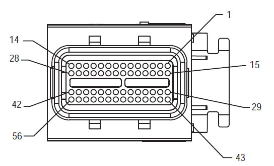
56-Way Cütləşmə Connector View
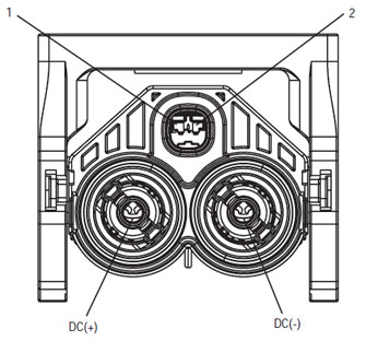
High Voltage DC Connector View Yazaki Connector
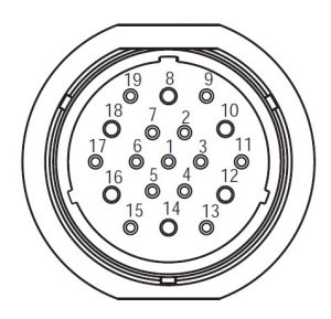
Mating Connector View Deutsch 19 – yol
QEYD: baxın Eaton Hybrid Komponent və Connector Yer MY08 Systems Connector yerler üçün
Uyarılar & xəbərdarlıq
təhlükə: Danger göstərilən prosedura riayət etməyən əgər ciddi xəsarət və ya həlak olacaq göstərir.
xəbərdarlıq: Warning dərhal təhlükə göstərir, Siz göstərilən prosedura riayət etməyən əgər ağır şəxsi zədə ilə nəticələnə bilər.
Xəbərdar: Diqqət siz göstərilən prosedura riayət etməyən əgər avtomobilin və ya maddi ziyan verə bilər göstərir.
Qeyd: Qeyd komponenti / sisteminin diaqnostika və ya təmir yardım edəcək əlavə ətraflı göstərir.
şəxsi zədə qarşısını almaq üçün göstərilən qaydada müəyyən prosedurları edin:
1. yüksək gərginlikli konusları avtomobilin ətrafında və lokavt məntəqə seçki komissiyasına yüklüyse, avtomobili işə icazə verilməlidir yeganə şəxs lockout tag imzalanmış şəxs.
2. bir vasitə iş və ya kabin getməzdən əvvəl mühərrik çalışırken, Siz "N" shift qolu yerləşdirmək lazımdır park əyləci müəyyən, və təkərlər qarşısını almaq.
3. təhlükəsizlik səbəblərə görə, həmişə əvvəl "N." dan Ötürücü mövqelərini seçilməsi xidmət əyləc məşğul
4. bir vasitə həmişə sürücü oturacağı əyləşdirilmək başlayan əvvəl, shift nəzarət "N" seçin, və park əyləc müəyyən.
5. ePTO ilə vasitələrdə olan, mühərrik və / və ya
Motor / Generator ePTO rejimində başlaya bilərsiniz. Hər hansı bir texniki xidmət yerinə və ya avtomobilin iş heç vaxt, Bu rejimdə isə.
6. 12-Volt Battery müsbət (+) və mənfi (-) Hər hansı bir Hybrid təchiz vasitə hər hansı bir qaynaq əvvəl dağınıq olmalıdır.
Xəbərdar: avadanlıq qəza və ya zərər qarşısını almaq üçün göstərilən qaydada müəyyən prosedurları edin.
Xəbərdar: Dayanacaq əyləcini azad və ya hava təzyiqi düzgün səviyyədə qədər Ötürücü seçmək üçün cəhd etməyin.
Xəbərdar: yedək yerdə zamanı "N" shift qolu ötürülməsi zərər qarşısını almaq və torpaq off sürücü təkərlər qaldırmaq və ya xarakteristikalarını ayırmaq.
High-Voltage Xəbərdarlıq & xəbərdarlıq
- CO2 və ya Quru kimyəvi Fire Extinguishers istifadə.
- yüksək gərginlikli wiring narıncı izolyasiya və ya convoluted borular əhatə və bağlayıcı xəbərdarlıq yazıları ilə qeyd olunur.
- Bütün Eaton® Hybrid Diesel / Electric vasitələri qeyd olunacaq "Hybrid’ Avtomobilin xarici, tire shift etiket ilə birlikdə.
- şassi monte hibrid komponentləri xüsusi yeri üçün OEM baxın.
- narıncı yüksək gərginlikli kabellər doğranır etməyin.
- Məntəqə seçki kəsilmiş və ya açmaq etməyin.
- doğranır və ya DC / DC Converter açmaq etməyin.
- doğranır və ya Inverter açmaq etməyin.
A bufer zona qurmaq lazımdır və yüksək gərginlikli rezin əlcək izolyasiya (sinif 0 dəri müdafiəçiləri ilə) yüksək gərginlikli üzərində işləyir əvvəl tələb olunur. Bu təlimatlara əməl edilməməsi ağır şəxsi xəsarəti və ya ölümlə nəticələnə bilər.
yüksək gərginlikli sistemi üzrə iş isə geyilən edilməlidir rezin izolyasiya əlcəklər sinif 0 dəri müdafiəçiləri ilə. rezin əlcəklər page "Diagnostic Tools / Service Nəşrlər" tapıldı rezin izolyasiya əlcəklər test proseduru aşağıdakı HƏR istifadə etməzdən əvvəl test etmək lazımdır 6. Bu təlimatlara əməl edilməməsi ağır şəxsi xəsarəti və ya ölümlə nəticələnə bilər.
səhifə "Yüksək gərginlikli Service Kapatma və Power-Up Qaydası" yoxladıqdan və ya hər hansı yüksək gərginlikli kabellər və ya komponentləri üzrə iş əvvəl 4 təqib edilməlidir. Bu təlimatlara əməl edilməməsi ağır şəxsi xəsarəti və ya ölümlə nəticələnə bilər.
Lockout və Tagout cihazlar yalnız vasitə Lockout və Tagout cihazlar yerləşdirilmiş texnik tərəfindən çıxarılmalıdır. Bu təlimatlara əməl edilməməsi ağır şəxsi xəsarəti və ya ölümlə nəticələnə bilər.
Yüksək gərginlikli rezin izolyasiya əlcəklər (sinif 0 dəri müdafiəçiləri ilə) hər hansı bir iş zaman geyilən edilməlidir
yüksək gərginlikli kabellər. səhifə "Yüksək gərginlikli Service Kapatma və Power-Up qaydası" 4 Hər hansı bir yüksək gərginlikli kabellər aradan qaldırılması əvvəl əməl olunmalıdır. Bu təlimatlara əməl edilməməsi ağır şəxsi xəsarəti və ya ölümlə nəticələnə bilər.
Yüksək gərginlikli kabellər və məftil narıncı və bağlayıcı bir xəbərdarlıq etiket olan. Yüksək gərginlikli komponentləri bir etiket ilə qeyd olunur. Yüksək gərginlikli rezin izolyasiya əlcəklər (sinif 0 dəri müdafiəçiləri ilə) bu komponentlərin hər hansı bir iş zaman istifadə olunmalıdır. Bu təlimatlara əməl edilməməsi ağır şəxsi xəsarəti və ya ölümlə nəticələnə bilər.
High-Voltage Service Kapatma qaydası
 1. Follow "High-Voltage İş üçün" qaydası.
2. Məntəqə seçki komissiyasının qarşısında qırmızı PEC Service Switch tapın və təkan söndürün.
3. Service Switch qapağını çıxarın və Lockout Bracket bərpa (J48506).
4. Lockout Asqı bağlamaq tag.
5. off mövqe hərəkət edə bilməz PEC Service Switch təmin.
6. sistem minimum üçün müəyyən imkan verir 5 dəqiqə yüksək gərginlikli yerinə.
7. ServiceRanger qoşun və Data Monitor PID keçirmək 116 "Yüksək Gərginlikli Batareya potensial." Deyilir istifadə SPN 520323 J1939 qoşulması üçün "Batareya Voltaj RB" (Relay Box).
8. gərginlik olmalıdır 30 volt və ya daha az. gərginlik yuxarıda varsa 30 volt, avtomobilin iş və 1-800-826-HELP at Eaton® əlaqə yoxdur (4357).
9. alovlanma düyməsini söndürün və təmir və ya sorun giderme addım davam.
Qeyd: gərginlik əsas off zaman sıfıra düşür.
High-Voltage Service Power-Up qaydası
1. Onların kilidli mövqelərini bütün yüksək gərginlikli bağlayıcı Yükle.
2. Əgər şəxs avtomobilin üzərində işləyir, Lockout Asqı və tag aradan qaldırılması.
3. Service Switch üzərində Lockout Bracket yeniden.
4. Service Pull out Switch və vasitə dəsti imkan 2 dəqiqə.
5. müvafiq olduqda avtomobili işə.
Eaton Hybrid Komponent və Connector Yer

Eaton Hybrid Komponent və Connector Yer MY09 Systems

STEP 1. AHBS mövcud doğrulayın.
- Gözdən və əməl Uyarılar & xəbərdarlıq.
- 9-Way Diagnostic Connector istifadə ServiceRanger ilə Active günah kodları və AHBS Qızlar.
təhlükə: Görmək High-Voltage Service Kapatma və Power-Up qaydası. şok qarşısını almaq üçün prosedurları edin, düzgün ele yüksək gərginlikli yandırmaq və ya ölüm. - Hansı AHBS mövcuddur
- Fault Kod varsa 116 IMF 14 Xahiş edirik, seçin, Addım getmək 9.
- Fault Kod varsa 116 IMF 10 Xahiş edirik, seçin, Addım getmək 2.
- If no Fault Codes are listed, The Service Switch was pushed in. Addım get 10.
STEP 2. Verify Data Monitor parameters.
- üzrə əsas.
- kabin 9-Way Diagnostic Connector ServiceRanger qoşun.
- "Data Monitor" opsiyasını seçin.
- View the Battery Pack Voltage (BCU1) PID 118 in the high- voltage Battery list:
- If the Battery Pack Voltage (BCU1) PID 118 is greater than 200 volt, Addım getmək 3.
- If the Battery Pack Voltage (BCU1) PID 118 az 200 volt, Power Electronics Carrier əvəz (PEC), sonra addım getmək 10.
STEP 3. Verify continuity of Inverter connector circuits.
- Key off.
- If the vehicle is not equipped with a DC/DC Converter or APG, skip this step.
- Using ASTM Class 0 electrical insulating rubber gloves with leather protectors, disconnect the DC cable for the DC/DC Converter and APG at the PEC.
- With the key off, temporarily remove the Lockout Bracket and pull the Service Switch out.
- üzrə əsas.
- Fault Kodu 116 IMF 10 still Active in ServiceRanger?
- Fault Kod varsa 116 IMF 10 is Active with the DC/DC Converter and APG disconnected, Addım getmək 4.
- Fault Kod varsa 116 IMF 10 is no longer Active with the DC/DC Converter and APG disconnected, key off and reinstall the Lockout Bracket on the PEC. Replace the Power Electronics Carrier (PEC), sonra addım getmək 10.
STEP 4. Verify continuity of PEC connector circuits to ground.
- Key off.
- Məntəqə seçki 19-Way Connector ayırın.
- Temporarily remove the Lockout Bracket and pull the Service Switch out.
Qeyd: Ensure the Key Switch is off. - Measure resistance at the PEC 19-Way Connector Terminal at the following pins:
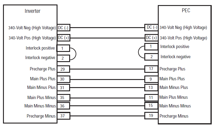
- Pin 17 Pin üçün 19
- Pin 9 Pin üçün 11
- Pin 13 Pin üçün 15
- If the resistance between Pins 17 və Pin 19 112-122 ohms və Pin olan müqavimət 9 Pin üçün 11 və Pin 13 Pin üçün 15 Hər 33-37 ohms var, Addım getmək 5.
- müqavimət sıra həyata Əgər, Addım getmək 6.
STEP 5. Verify continuity of Inverter connector circuits to ground.
- Key off.
- Reconnect the PEC 19-Way Connector.
- Inverter 56-Way Connector ayırın.
- Inspect the connector pins for damaged, corroded and/or loose wires.
- Measure resistance between the Inverter 56-Way Connector at the following pins:
- Pin 29 Pin üçün 37
- Pin 30 Pin üçün 35
- Pin 31 Pin üçün 36 Qeyd: müqavimət dəyərlər monitorinq isə yumşaq Connector yaxın Inverter 56-Way Connector Harness Flex.
- Pin arasında müqavimət 29 və Pin 37 112-122 ohms və Pin olan müqavimət 30 Pin üçün 35 və Pin 31 Pin üçün 36 Hər 33-37 ohms var, push the Service Switch on the PEC and reinstall the Lockout Bracket. Addım get 8.
- müqavimət sıra həyata Əgər, repair the Hybrid Harness between the PEC and Inverter, sonra addım getmək 10.
STEP 6. Verify continuity of PEC connector circuits.
- Key off.
- Remove the Air Filter Cover and Air Filter from the PEC. Refer to TRSM1000 for procedures.*
- An Inertia Switch is located at the front of the PEC inside the box and viewable when the Air Filter is removed.
- Using ASTM Class 0 electrical insulating rubber gloves with leather protectors, press the button on the top of the Inertia Switch until heard or felt a click. This switch must be depressed a set distance to reset the switch.
- Measure resistance at the PEC 19-Way Connector Terminal at the following pins:
- Pin 17 Pin üçün 19
- Pin 9 Pin üçün 11
- Pin 13 Pin üçün 15
- qIf the resistance between Pin 17 və Pin 19 112-122 ohms və Pin olan müqavimət 9 Pin üçün 11 və Pin 13 Pin üçün 15 Hər 33-37 ohms var, the Inertia Switch was tripped. Test is complete. Addım get 10.
- müqavimət sıra həyata Əgər, push in the Service Switch on the PEC and reinstall the Lockout Bracket, sonra addım getmək 7.
STEP 7. Verify continuity of Inverter connector circuits.
- Key off.
- Disconnect the DC High-Voltage Cable at the PEC Bulkhead and at the Inverter Bulkhead.
- Measure resistance between the Low-Voltage Interlock Pins on the PEC side of the DC High-Voltage Cable:
Qeyd: The Interlock Pins are the two small spade terminals located in the same opening.- If the resistance is 0–0.3 ohms between the Interlock Loop Pins, Power Electronics Carrier əvəz (PEC), sonra addım getmək 10.
- müqavimət sıra həyata Əgər, DC yüksək gərginlikli kabel əvəz, sonra addım getmək 10.
STEP 8. Verify continuity of DC Cable from PEC to Inverter Connector circuits.
- Key off.
- Disconnect the DC High-Voltage Cable at the PEC Bulkhead and the Inverter Bulkhead.
- Measure the resistance of each high-voltage circuit on the cable:
- If the resistance of each high-voltage circuit in the cable is 1 ohm və ya daha az, Inverter əvəz, sonra addım getmək 10.
- müqavimət sıra həyata Əgər, replace the DC High-Voltage Cable, sonra addım getmək 10.
STEP 9. Verify Data Monitor parameters.
- kabin 9-Way Diagnostic Connector ServiceRanger qoşun.
- "Data Monitor" opsiyasını seçin.
- View the following parameters in the High-Voltage Battery list.
- Battery Pack Voltage (BCU1) PID 118
- Battery Voltage PID 116
- If the voltage readings on PID 116 və PID 118 are within 10 bir-birinin volt, Power Electronics Carrier əvəz (PEC), sonra addım getmək 10.
- If the voltage readings on PID 116 və PID 118 are greater than 10 bir-birinin volt, Inverter əvəz, sonra addım getmək 10.
STEP 10. təmir doğrulayın.
- Key off.
- bütün bağlayıcı və mənfi batareya kabel təkrar.
- üzrə əsas.
- Clear kodları, görmək Clear Effektiv Faults.
- avtomobilin sürücü və kodu yenidən cəhd.
- kodları yoxlayın, görmək Aktiv və Inactive çatışmazlıqlar bax.
- heç bir kodları varsa, test tam.
- Fault Kod varsa 116 görünür, contact Eaton at 1- 800-826-HELP (4357). Repeat this Step (addım 10).
- daha code başqa varsa 116 görünür, görmək Kodu Index siyahısı Fault.
Hər hansı ötürülməsi hissəsi biz var lazımdır! Eyni gün göndərmə mövcuddur, dünyada.
BİZİM ekspertlərdən biri PULSUZ DƏSTƏK lazımdır?