[fusion_builder_container hundred_percent=”no” hundred_percent_height=”no” hundred_percent_height_scroll=”no” hundred_percent_height_center_content=”yes” equal_height_columns=”no” menu_anchor=”” hide_on_mobile=”small-visibility,medium-visibility,large-visibility” status=”published” publish_date=”” class=”” id=”” background_color=”” background_image=”” background_position=”center center” background_repeat=”no-repeat” fade=”no” background_parallax=”none” enable_mobile=”no” parallax_speed=”0.3″ video_mp4=”” video_webm=”” video_ogv=”” video_url=”” video_aspect_ratio=”16:9″ video_loop=”yes” video_mute=”yes” video_preview_image=”” border_size=”” border_color=”” border_style=”solid” margin_top=”35″ margin_bottom=”” padding_top=”” padding_right=”” padding_bottom=”” padding_left=””][fusion_builder_row][fusion_builder_column type=”1_1″ layout=”1_1″ spacing=”” center_content=”no” link=”” target=”_self” min_height=”” hide_on_mobile=”small-visibility,medium-visibility,large-visibility” class=”” id=”” background_color=”” background_image=”” background_image_id=”” background_position=”left top” background_repeat=”no-repeat” hover_type=”none” border_size=”0″ border_color=”” border_style=”solid” border_position=”all” padding_top=”” padding_right=”” padding_bottom=”” padding_left=”” margin_top=”” margin_bottom=”” animation_type=”” animation_direction=”left” animation_speed=”0.3″ animation_offset=”” last=”no”][fusion_text columns=”” column_min_width=”” column_spacing=”” rule_style=”default” rule_size=”” rule_color=”” hide_on_mobile=”small-visibility,medium-visibility,large-visibility” class=”” id=””]

Eaton Fuller Hybrid Transmission Fault Code 65 – ECA Speed Sensor

[/fusion_text][/fusion_builder_column][/fusion_builder_row][/fusion_builder_container][fusion_builder_container hundred_percent=”no” hundred_percent_height=”no” hundred_percent_height_scroll=”no” hundred_percent_height_center_content=”yes” equal_height_columns=”no” menu_anchor=”” hide_on_mobile=”small-visibility,medium-visibility,large-visibility” status=”published” publish_date=”” class=”” id=”” background_color=”” background_image=”” background_position=”center center” background_repeat=”no-repeat” fade=”no” background_parallax=”none” enable_mobile=”no” parallax_speed=”0.3″ video_mp4=”” video_webm=”” video_ogv=”” video_url=”” video_aspect_ratio=”16:9″ video_loop=”yes” video_mute=”yes” video_preview_image=”” border_size=”” border_color=”” border_style=”solid” margin_top=”” margin_bottom=”” padding_top=”” padding_right=”” padding_bottom=”” padding_left=””][fusion_builder_row][fusion_builder_column type=”1_1″ layout=”1_1″ spacing=”” center_content=”no” link=”” target=”_self” min_height=”” hide_on_mobile=”small-visibility,medium-visibility,large-visibility” class=”” id=”” background_color=”” background_image=”” background_image_id=”” background_position=”left top” background_repeat=”no-repeat” hover_type=”none” border_size=”0″ border_color=”” border_style=”solid” border_position=”all” padding_top=”” padding_right=”” padding_bottom=”” padding_left=”” margin_top=”” margin_bottom=”” animation_type=”” animation_direction=”left” animation_speed=”0.3″ animation_offset=”” last=”no”][fusion_text columns=”” column_min_width=”” column_spacing=”” rule_style=”default” rule_size=”” rule_color=”” hide_on_mobile=”small-visibility,medium-visibility,large-visibility” class=”” id=””]

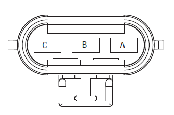
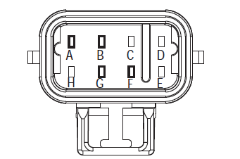
Fault code for Eaton Hybrid Drive Systems models (MY08) EH-8E306A-U, EH-8E306A-UPG, EH-8E306A-UP, EH-8E306A-CD, EH-8E306A-T, EH-6E606B-CD, (MY09) EH-8E406A-U/P, EH-8E406A-UP, EH-8E406A-UPG, EH-8E406A-CD, EH-8E406A-CDG, EH-8E406A-CDR, EH-8E406A-T, EH-6E706B-CD, EH-6E706B-P and EH-6E706B-UPG. Read below to learn how to test, clear and fix fault code errors for your Freightliner, Mack, Peterbilt, Kenworth, Volvo, International, and heavy-duty truck and equipment. The Electric Clutch Actuator (ECA) controls the position of the clutch assembly. The ECA has a main power 3-Way Connector that is directly connected to the 12-Volt Battery and an 8-Way Connector that is connected to inputs like the Hybrid Control Module (HCM) and the Engine Speed Sensor. The ECA communicates with the HCM over the proprietary Controller Area Network (CAN) data link to change position, show faults, or include other operation information.

Fault Code 65 – ECA Speed Sensor Detection

The following preconditions must be met before the system detects the fault:

  • ECA ignition voltage is greater than 8.5 volts.
  • Fault Code 18 or 87 are Active.

Note: When troubleshooting an Inactive code refer to the Product Diagnostic Mode (PDM)

Conditions to Set Fault Code Active

  • FMI 2 is set when the HCM detects engine speed at idle, but does not detect ECA engine speed.
  • FMI 5 is set when the ECA detects an open on the ECA Speed Sensor signal circuit at key on.

Fallback When Fault Code 65 is set the following conditions occur:

  • Amber “Check Hybrid” light illuminates.
  • Fault is stored in Hybrid Control Module (HCM) memory.

[/fusion_text][fusion_text columns=”” column_min_width=”” column_spacing=”” rule_style=”default” rule_size=”” rule_color=”” hide_on_mobile=”small-visibility,medium-visibility,large-visibility” class=”” id=””]

Conditions to Set Fault Code Inactive

Only Inactive faults can be cleared from the Transmission Electronic Control Unit (TECU) or HCM history using ServiceRanger. The TECU automatically clears the faults from history after 200 hours and the HCM automatically clears the faults from history after the fault has been Inactive for 200 hours.

This fault code can be caused by any of the following:

  • FMI 2, 5
    • ECA Speed Sensor
    • ECA Speed Sensor Harness
    • ECA

[/fusion_text][/fusion_builder_column][/fusion_builder_row][/fusion_builder_container][fusion_builder_container hundred_percent=”no” hundred_percent_height=”no” hundred_percent_height_scroll=”no” hundred_percent_height_center_content=”yes” equal_height_columns=”no” menu_anchor=”” hide_on_mobile=”small-visibility,medium-visibility,large-visibility” status=”published” publish_date=”” class=”” id=”” background_color=”” background_image=”” background_position=”center center” background_repeat=”no-repeat” fade=”no” background_parallax=”none” enable_mobile=”no” parallax_speed=”0.3″ video_mp4=”” video_webm=”” video_ogv=”” video_url=”” video_aspect_ratio=”16:9″ video_loop=”yes” video_mute=”yes” video_preview_image=”” border_size=”” border_color=”” border_style=”solid” margin_top=”” margin_bottom=”” padding_top=”” padding_right=”” padding_bottom=”” padding_left=””][fusion_builder_row][fusion_builder_column type=”1_1″ layout=”1_1″ spacing=”” center_content=”no” link=”” target=”_self” min_height=”” hide_on_mobile=”small-visibility,medium-visibility,large-visibility” class=”” id=”” background_color=”” background_image=”” background_image_id=”” background_position=”left top” background_repeat=”no-repeat” hover_type=”none” border_size=”0″ border_color=”” border_style=”solid” border_position=”all” padding_top=”” padding_right=”” padding_bottom=”” padding_left=”” margin_top=”” margin_bottom=”” animation_type=”” animation_direction=”left” animation_speed=”0.3″ animation_offset=”” last=”no”][fusion_text columns=”” column_min_width=”” column_spacing=”” rule_style=”default” rule_size=”” rule_color=”” hide_on_mobile=”small-visibility,medium-visibility,large-visibility” class=”” id=””]

Fault Code 65 – ECA Speed Sensor Test

[/fusion_text][/fusion_builder_column][/fusion_builder_row][/fusion_builder_container][fusion_builder_container hundred_percent=”no” hundred_percent_height=”no” hundred_percent_height_scroll=”no” hundred_percent_height_center_content=”yes” equal_height_columns=”no” menu_anchor=”” hide_on_mobile=”small-visibility,medium-visibility,large-visibility” status=”published” publish_date=”” class=”” id=”” background_color=”” background_image=”” background_position=”center center” background_repeat=”no-repeat” fade=”no” background_parallax=”none” enable_mobile=”no” parallax_speed=”0.3″ video_mp4=”” video_webm=”” video_ogv=”” video_url=”” video_aspect_ratio=”16:9″ video_loop=”yes” video_mute=”yes” video_preview_image=”” border_size=”” border_color=”” border_style=”solid” margin_top=”” margin_bottom=”” padding_top=”” padding_right=”” padding_bottom=”” padding_left=””][fusion_builder_row][fusion_builder_column type=”1_1″ layout=”1_1″ spacing=”” center_content=”no” link=”” target=”_self” min_height=”” hide_on_mobile=”small-visibility,medium-visibility,large-visibility” class=”” id=”” background_color=”” background_image=”” background_image_id=”” background_position=”left top” background_repeat=”no-repeat” hover_type=”none” border_size=”0″ border_color=”” border_style=”solid” border_position=”all” padding_top=”” padding_right=”” padding_bottom=”” padding_left=”” margin_top=”” margin_bottom=”” animation_type=”” animation_direction=”left” animation_speed=”0.3″ animation_offset=”” last=”no”][fusion_text columns=”” column_min_width=”” column_spacing=”” rule_style=”default” rule_size=”” rule_color=”” hide_on_mobile=”small-visibility,medium-visibility,large-visibility” class=”” id=””]

Component Identification:

[/fusion_text][/fusion_builder_column][fusion_builder_column type=”1_3″ layout=”1_2″ spacing=”” center_content=”no” link=”” target=”_self” min_height=”” hide_on_mobile=”small-visibility,medium-visibility,large-visibility” class=”” id=”” background_color=”” background_image=”” background_image_id=”” background_position=”left top” background_repeat=”no-repeat” hover_type=”none” border_size=”0″ border_color=”” border_style=”solid” border_position=”all” padding_top=”” padding_right=”” padding_bottom=”” padding_left=”” margin_top=”” margin_bottom=”” animation_type=”” animation_direction=”left” animation_speed=”0.3″ animation_offset=”” last=”no”][fusion_imageframe image_id=”14378|full” max_width=”” style_type=”” blur=”” stylecolor=”” hover_type=”none” bordersize=”” bordercolor=”” borderradius=”” align=”center” lightbox=”no” gallery_id=”” lightbox_image=”” lightbox_image_id=”” alt=”ECA 3-Way Connector for Eaton Fuller transmission” link=”” linktarget=”_self” hide_on_mobile=”small-visibility,medium-visibility,large-visibility” class=”” id=”” animation_type=”” animation_direction=”left” animation_speed=”0.3″ animation_offset=””]https://www.globaltransmissionsupply.com/wp-content/uploads/ECA-3-way-connector.png[/fusion_imageframe][fusion_text columns=”” column_min_width=”” column_spacing=”” rule_style=”default” rule_size=”” rule_color=”” hide_on_mobile=”small-visibility,medium-visibility,large-visibility” class=”” id=””]

ECA 3-Way Connector

[/fusion_text][/fusion_builder_column][fusion_builder_column type=”1_3″ layout=”1_2″ spacing=”” center_content=”no” link=”” target=”_self” min_height=”” hide_on_mobile=”small-visibility,medium-visibility,large-visibility” class=”” id=”” background_color=”” background_image=”” background_image_id=”” background_position=”left top” background_repeat=”no-repeat” hover_type=”none” border_size=”0″ border_color=”” border_style=”solid” border_position=”all” padding_top=”” padding_right=”” padding_bottom=”” padding_left=”” margin_top=”” margin_bottom=”” animation_type=”” animation_direction=”left” animation_speed=”0.3″ animation_offset=”” last=”no”][fusion_imageframe image_id=”14376|full” max_width=”” style_type=”” blur=”” stylecolor=”” hover_type=”none” bordersize=”” bordercolor=”” borderradius=”” align=”center” lightbox=”no” gallery_id=”” lightbox_image=”” lightbox_image_id=”” alt=”Eaton Fuller transmission ECA speed sensor” link=”” linktarget=”_self” hide_on_mobile=”small-visibility,medium-visibility,large-visibility” class=”” id=”” animation_type=”” animation_direction=”left” animation_speed=”0.3″ animation_offset=””]https://www.globaltransmissionsupply.com/wp-content/uploads/ECA-Speed-Sensor.png[/fusion_imageframe][fusion_text columns=”” column_min_width=”” column_spacing=”” rule_style=”default” rule_size=”” rule_color=”” hide_on_mobile=”small-visibility,medium-visibility,large-visibility” class=”” id=””]

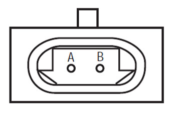
ECA Speed Sensor (Connect View)

[/fusion_text][/fusion_builder_column][fusion_builder_column type=”1_3″ layout=”1_2″ spacing=”” center_content=”no” link=”” target=”_self” min_height=”” hide_on_mobile=”small-visibility,medium-visibility,large-visibility” class=”” id=”” background_color=”” background_image=”” background_image_id=”” background_position=”left top” background_repeat=”no-repeat” hover_type=”none” border_size=”0″ border_color=”” border_style=”solid” border_position=”all” padding_top=”” padding_right=”” padding_bottom=”” padding_left=”” margin_top=”” margin_bottom=”” animation_type=”” animation_direction=”left” animation_speed=”0.3″ animation_offset=”” last=”no”][fusion_imageframe image_id=”14377|full” max_width=”” style_type=”” blur=”” stylecolor=”” hover_type=”none” bordersize=”” bordercolor=”” borderradius=”” align=”center” lightbox=”no” gallery_id=”” lightbox_image=”” lightbox_image_id=”” alt=”ECA 8-way connector for Eaton Fuller transmission” link=”” linktarget=”_self” hide_on_mobile=”small-visibility,medium-visibility,large-visibility” class=”” id=”” animation_type=”” animation_direction=”left” animation_speed=”0.3″ animation_offset=””]https://www.globaltransmissionsupply.com/wp-content/uploads/ECA-8-way-connector.png[/fusion_imageframe][fusion_text columns=”” column_min_width=”” column_spacing=”” rule_style=”default” rule_size=”” rule_color=”” hide_on_mobile=”small-visibility,medium-visibility,large-visibility” class=”” id=””]

ECA 8-Way Connector

[/fusion_text][/fusion_builder_column][fusion_builder_column type=”1_1″ layout=”1_1″ spacing=”” center_content=”no” link=”” target=”_self” min_height=”” hide_on_mobile=”small-visibility,medium-visibility,large-visibility” class=”” id=”” background_image_id=”” background_color=”#000000″ background_image=”” background_position=”left top” undefined=”” background_repeat=”no-repeat” hover_type=”none” border_size=”0″ border_color=”” border_style=”solid” border_position=”all” padding_top=”” padding_right=”” padding_bottom=”” padding_left=”” margin_top=”” margin_bottom=”” animation_type=”” animation_direction=”left” animation_speed=”0.3″ animation_offset=”” last=”no”][fusion_text columns=”” column_min_width=”” column_spacing=”” rule_style=”default” rule_size=”” rule_color=”” hide_on_mobile=”small-visibility,medium-visibility,large-visibility” class=”” id=””]

NOTE: Refer to the Eaton Hybrid Component and Connector Location for Connector Locations in MY08 Systems

[/fusion_text][/fusion_builder_column][fusion_builder_column type=”1_1″ layout=”1_1″ spacing=”” center_content=”no” link=”” target=”_self” min_height=”” hide_on_mobile=”small-visibility,medium-visibility,large-visibility” class=”” id=”” background_image_id=”” background_color=”#000000″ background_image=”” background_position=”left top” undefined=”” background_repeat=”no-repeat” hover_type=”none” border_size=”0″ border_color=”” border_style=”solid” border_position=”all” padding_top=”” padding_right=”” padding_bottom=”” padding_left=”” margin_top=”20″ margin_bottom=”20″ animation_type=”” animation_direction=”left” animation_speed=”0.3″ animation_offset=”” last=”no”][fusion_text columns=”” column_min_width=”” column_spacing=”” rule_style=”default” rule_size=”” rule_color=”” hide_on_mobile=”small-visibility,medium-visibility,large-visibility” class=”” id=””]

NOTE: Refer to the Eaton Hybrid Component and Connector Location for Connector Locations in MY09 Systems.
[/fusion_text][/fusion_builder_column][fusion_builder_column type=”1_1″ layout=”1_1″ spacing=”” center_content=”no” link=”” target=”_self” min_height=”” hide_on_mobile=”small-visibility,medium-visibility,large-visibility” class=”” id=”” background_color=”” background_image=”” background_image_id=”” background_position=”left top” background_repeat=”no-repeat” hover_type=”none” border_size=”0″ border_color=”” border_style=”solid” border_position=”all” padding_top=”” padding_right=”” padding_bottom=”” padding_left=”” margin_top=”” margin_bottom=”” animation_type=”” animation_direction=”left” animation_speed=”0.3″ animation_offset=”” last=”no”][fusion_imageframe image_id=”14379|full” max_width=”” style_type=”” blur=”” stylecolor=”” hover_type=”none” bordersize=”” bordercolor=”” borderradius=”” align=”center” lightbox=”no” gallery_id=”” lightbox_image=”” lightbox_image_id=”” alt=”Speed sensor ECA connector location” link=”” linktarget=”_self” hide_on_mobile=”small-visibility,medium-visibility,large-visibility” class=”” id=”” animation_type=”” animation_direction=”left” animation_speed=”0.3″ animation_offset=””]https://www.globaltransmissionsupply.com/wp-content/uploads/Spped-sensor-ECO-connector-location.jpg[/fusion_imageframe][/fusion_builder_column][/fusion_builder_row][/fusion_builder_container][fusion_builder_container hundred_percent=”no” hundred_percent_height=”no” hundred_percent_height_scroll=”no” hundred_percent_height_center_content=”yes” equal_height_columns=”no” menu_anchor=”” hide_on_mobile=”small-visibility,medium-visibility,large-visibility” status=”published” publish_date=”” class=”” id=”” background_color=”” background_image=”” background_position=”center center” background_repeat=”no-repeat” fade=”no” background_parallax=”none” enable_mobile=”no” parallax_speed=”0.3″ video_mp4=”” video_webm=”” video_ogv=”” video_url=”” video_aspect_ratio=”16:9″ video_loop=”yes” video_mute=”yes” video_preview_image=”” border_size=”” border_color=”” border_style=”solid” margin_top=”” margin_bottom=”” padding_top=”” padding_right=”” padding_bottom=”” padding_left=””][fusion_builder_row][fusion_builder_column type=”1_1″ layout=”1_1″ spacing=”” center_content=”no” link=”” target=”_self” min_height=”” hide_on_mobile=”small-visibility,medium-visibility,large-visibility” class=”” id=”” background_color=”” background_image=”” background_image_id=”” background_position=”left top” background_repeat=”no-repeat” hover_type=”none” border_size=”0″ border_color=”” border_style=”solid” border_position=”all” padding_top=”” padding_right=”” padding_bottom=”” padding_left=”” margin_top=”” margin_bottom=”” animation_type=”” animation_direction=”left” animation_speed=”0.3″ animation_offset=”” last=”no”][fusion_modal name=”warnings_cautions” title=”Warnings & Cautions” size=”large” background=”” border_color=”” show_footer=”yes” class=”” id=””]Danger: Danger indicates you will be severely injured or killed if do not follow the indicated procedure.
Warning: Warning indicates an immediate hazard, which could result in severe personal injury if you do not follow the indicated procedure.
Caution: Caution indicates vehicle or property damage could occur if you do not follow the indicated procedure.

 Note: Note indicates additional detail that will aid in the diagnosis or repair of a component/system.

Follow the specified procedures in the indicated order to avoid personal injury:

1. If the high-voltage cones are around the vehicle and the lockout is installed on the PEC, the only person that should be allowed to start the vehicle is the person who signed the lockout tag.
2. Before working on a vehicle or leaving the cab while the engine is running, you should place the shift lever in “N” set the parking brake, and block the wheels.
3. For safety reasons, always engage the service brakes prior to selecting gear positions from “N.”
4. Before starting a vehicle always be seated in the driver’s seat, select “N” on the shift control, and set the parking brakes.
5. In vehicles with ePTO, the engine and/or
Motor/Generator can start in ePTO mode. Never perform any maintenance or work on vehicle, while in this mode.
6. 12-Volt Battery positive (+) and negative (-) must be disconnected prior to any welding on any Hybrid equipped vehicle.

Caution: Follow the specified procedures in the indicated order to avoid equipment malfunction or damage.
Caution: Do not release the parking brake or attempt to select a gear until the air pressure is at the correct level.
Caution: To avoid damage to the transmission during towing place the shift lever in “N” and lift the drive wheels off the ground or disconnect the driveline.

High-Voltage Warnings & Cautions

  • Use CO2 or Dry Chemical Fire Extinguishers.
  • The high-voltage wiring is covered in orange insulation or convoluted tubing and marked with warning labels at the connectors.
  • All Eaton® Hybrid Diesel/Electric vehicles will be marked ‘Hybrid’ on the outside of the vehicle, along with the shift label on the dash.
  • Refer to OEM for specific location of chassis mounted hybrid components.
  • Do NOT cut into the orange high-voltage cables.
  • Do NOT cut into or open the PEC.
  • Do NOT cut into or open the DC/DC Converter.
  • Do NOT cut into or open the Inverter.

A buffer zone must be set up and high-voltage insulated rubber gloves (class 0 with leather protectors) are required prior to working on high-voltage. Failure to follow these instructions may result in severe personal injury or death.
The rubber-insulated gloves that must be worn while working on the high-voltage system are class 0 with leather protectors. The rubber gloves should be tested before EVERY use following the rubber insulation gloves testing procedure found in “Diagnostic Tools/Service Publications” on page 6. Failure to follow these instructions may result in severe personal injury or death.
Before inspecting or working on any high-voltage cables or components the “High-Voltage Service Shutdown and Power-Up Procedure” on page 4 should be followed. Failure to follow these instructions may result in severe personal injury or death.
The Lockout and Tagout devices should only be removed by the technician that placed the Lockout and Tagout devices on the vehicle. Failure to follow these instructions may result in severe personal injury or death.
High-voltage rubber insulated gloves (class 0 with leather protectors) must be worn when working on any
high-voltage cables. The “High-Voltage Service Shutdown and Power-Up Procedure” on page 4 must be followed prior to removing any high-voltage cables. Failure to follow these instructions may result in severe personal injury or death.
High-voltage cables and wiring are orange and contain a warning label at the connectors. High-voltage components are marked with a label. High-voltage rubber insulated gloves (class 0 with leather protectors) must be used when working on any of these components. Failure to follow these instructions may result in severe personal injury or death.

High-Voltage Service Shutdown Procedures

High-Voltage Service Shutdown and Power-Up Procedure1. Follow “High-Voltage Work Area” procedure.
2. Locate the red PEC Service Switch on the front of the PEC and push switch off.
3. Remove the Service Switch Cover and install the Lockout Bracket (J48506).
4. Fasten tag to the Lockout Bracket.
5. Ensure the PEC Service Switch can not move from the off position.
6. Allow the system to set for a minimum of 5 minutes to discharge high voltage.
7. Connect ServiceRanger and view the Data Monitor PID 116 called “High-Voltage Battery Potential.” Use SPN 520323 for J1939 connection “Battery Voltage RB” (Relay Box).
8. The voltage should be 30 volts or less. If the voltage is above 30 volts, do not work on the vehicle and contact Eaton® at 1-800-826-HELP (4357).
9. Turn ignition key off and proceed to repair or troubleshooting step.
Note: The voltage drops to zero when the key is off.

High-Voltage Service Power-Up Procedure

1. Install all high-voltage connectors into their locked positions.
2. If you are the person working on the vehicle, remove the Lockout Bracket and tag.
3. Reinstall the Lockout Bracket over the Service Switch.
4. Pull the Service Switch out and let vehicle set for 2 minutes.
5. Start vehicle when appropriate.[/fusion_modal][fusion_modal name=”component_location” title=”Eaton Hybrid Component and Connector Location ” size=”large” background=”#ffffff” border_color=”” show_footer=”yes” class=”” id=””]

Eaton Hybrid Component and Connector Locations MY08 Systems

[/fusion_modal][fusion_modal name=”component_location2″ title=”Eaton Hybrid Component and Connector Location MY09 Systems” size=”large” background=”#ffffff” border_color=”” show_footer=”yes” class=”” id=””]

Eaton Hybrid Component and Connector Locations MY09 Systems

[/fusion_modal][/fusion_builder_column][/fusion_builder_row][/fusion_builder_container][fusion_builder_container hundred_percent=”no” hundred_percent_height=”no” hundred_percent_height_scroll=”no” hundred_percent_height_center_content=”yes” equal_height_columns=”no” menu_anchor=”” hide_on_mobile=”small-visibility,medium-visibility,large-visibility” status=”published” publish_date=”” class=”” id=”” background_color=”” background_image=”” background_position=”center center” background_repeat=”no-repeat” fade=”no” background_parallax=”none” enable_mobile=”no” parallax_speed=”0.3″ video_mp4=”” video_webm=”” video_ogv=”” video_url=”” video_aspect_ratio=”16:9″ video_loop=”yes” video_mute=”yes” video_preview_image=”” border_size=”” border_color=”” border_style=”solid” margin_top=”” margin_bottom=”” padding_top=”” padding_right=”” padding_bottom=”” padding_left=””][fusion_builder_row][fusion_builder_column type=”1_1″ layout=”1_1″ spacing=”” center_content=”no” link=”” target=”_self” min_height=”” hide_on_mobile=”small-visibility,medium-visibility,large-visibility” class=”” id=”” background_color=”” background_image=”” background_image_id=”” background_position=”left top” background_repeat=”no-repeat” hover_type=”none” border_size=”0″ border_color=”” border_style=”solid” border_position=”all” padding_top=”” padding_right=”” padding_bottom=”” padding_left=”” margin_top=”” margin_bottom=”” animation_type=”” animation_direction=”left” animation_speed=”0.3″ animation_offset=”” last=”no”][fusion_content_boxes layout=”clean-horizontal” columns=”1″ title_size=”18px” heading_size=”3″ title_color=”#ffffff” body_color=”#ffffff” backgroundcolor=”#4f4f4f” icon=”” iconflip=”” iconrotate=”” iconspin=”no” iconcolor=”” icon_circle=”” icon_circle_radius=”” circlecolor=”” circlebordersize=”” circlebordercolor=”” outercirclebordersize=”” outercirclebordercolor=”” icon_size=”” icon_hover_type=”” hover_accent_color=”” image=”” image_id=”” image_width=”” image_height=”” link_type=”” button_span=”” link_area=”” link_target=”” icon_align=”left” animation_type=”” animation_delay=”” animation_offset=”” animation_direction=”left” animation_speed=”0.3″ margin_top=”” margin_bottom=”” hide_on_mobile=”small-visibility,medium-visibility,large-visibility” class=”” id=””][fusion_content_box title=”STEP 1.Verify FMIs present.” backgroundcolor=”” icon=”” iconflip=”” iconrotate=”” iconspin=”no” iconcolor=”” circlecolor=”” circlebordersize=”” circlebordercolor=”” outercirclebordersize=”” outercirclebordercolor=”” image=”” image_id=”” image_width=”” image_height=”” link=”” linktext=”Read More” link_target=”” animation_type=”” animation_direction=”left” animation_speed=”0.3″ animation_offset=””]

  1.  Retrieve Active fault codes and FMIs with ServiceRanger using the 9-Way Diagnostic Connector or manually.
  2. Which FMIs are present?
    • If FMI 5 is listed, go to Step 2.
    • If FMI 2 is listed, go to Step 3.

[/fusion_content_box][/fusion_content_boxes][fusion_content_boxes layout=”clean-horizontal” columns=”2″ title_size=”18px” heading_size=”3″ title_color=”#ffffff” body_color=”#ffffff” backgroundcolor=”#4f4f4f” icon=”” iconflip=”” iconrotate=”” iconspin=”no” iconcolor=”” icon_circle=”” icon_circle_radius=”” circlecolor=”” circlebordersize=”” circlebordercolor=”” outercirclebordersize=”” outercirclebordercolor=”” icon_size=”” icon_hover_type=”” hover_accent_color=”” image=”” image_id=”” image_width=”” image_height=”” link_type=”” button_span=”” link_area=”” link_target=”” icon_align=”left” animation_type=”” animation_delay=”” animation_offset=”” animation_direction=”left” animation_speed=”0.3″ margin_top=”” margin_bottom=”” hide_on_mobile=”small-visibility,medium-visibility,large-visibility” class=”” id=””][fusion_content_box title=”STEP 2. Verify continuity of ECA Harness.” backgroundcolor=”” icon=”” iconflip=”” iconrotate=”” iconspin=”no” iconcolor=”” circlecolor=”” circlebordersize=”” circlebordercolor=”” outercirclebordersize=”” outercirclebordercolor=”” image=”” image_id=”” image_width=”” image_height=”” link=”” linktext=”Read More” link_target=”” animation_type=”” animation_direction=”left” animation_speed=”0.3″ animation_offset=””]

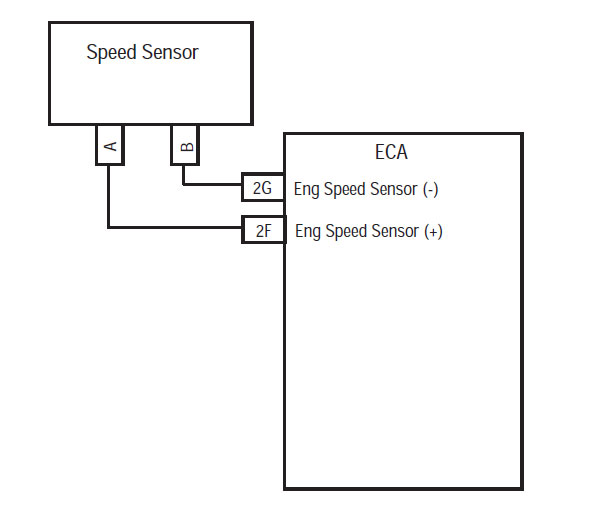
  1. Check resistance between ECA 8-Way Connector Pin F and Pin G:
    • If resistance between ECA 8-Way Connector Pin F and Pin G is 140–180 ohms, go to Step 3.
    • If resistance is out of range, repair the open in the sensor or the harness from the ECA to the Sensor, then go to Step 7.

[/fusion_content_box][fusion_content_box title=”STEP 3. Verify continuity of ECA Harness and ground.” backgroundcolor=”” icon=”” iconflip=”” iconrotate=”” iconspin=”” iconcolor=”” circlecolor=”” circlebordersize=”” circlebordercolor=”” outercirclebordersize=”” outercirclebordercolor=”” image=”” image_id=”” image_width=”” image_height=”” link=”” linktext=”” link_target=”” animation_type=”” animation_direction=”left” animation_speed=”0.3″ animation_offset=””]

  1. Key on.
  2. Check resistance between ECA 8-Way Connector Pin F and ground:
    • If resistance is 10K or greater, go to Step 4.
    • If resistance is out of range, repair the short to ground in the Sensor or the harness from the ECA to the Sensor, then go to Step 7.

[/fusion_content_box][/fusion_content_boxes][fusion_content_boxes layout=”clean-horizontal” columns=”2″ title_size=”18px” heading_size=”3″ title_color=”#ffffff” body_color=”#ffffff” backgroundcolor=”#4f4f4f” icon=”” iconflip=”” iconrotate=”” iconspin=”no” iconcolor=”” icon_circle=”” icon_circle_radius=”” circlecolor=”” circlebordersize=”” circlebordercolor=”” outercirclebordersize=”” outercirclebordercolor=”” icon_size=”” icon_hover_type=”” hover_accent_color=”” image=”” image_id=”” image_width=”” image_height=”” link_type=”” button_span=”” link_area=”” link_target=”” icon_align=”left” animation_type=”” animation_delay=”” animation_offset=”” animation_direction=”left” animation_speed=”0.3″ margin_top=”” margin_bottom=”” hide_on_mobile=”small-visibility,medium-visibility,large-visibility” class=”” id=””][fusion_content_box title=”STEP 4. Verify voltage of ECA Harness and ground.” backgroundcolor=”” icon=”” iconflip=”” iconrotate=”” iconspin=”no” iconcolor=”” circlecolor=”” circlebordersize=”” circlebordercolor=”” outercirclebordersize=”” outercirclebordercolor=”” image=”” image_id=”” image_width=”” image_height=”” link=”” linktext=”Read More” link_target=”” animation_type=”” animation_direction=”left” animation_speed=”0.3″ animation_offset=””]

  1. Key on.
  2. Measure voltage from the ECA 8-Way Connector Pin G and ground:
    • If voltage is 0 volts at key on and FMI 5 is Active, replace the Electric Clutch Actuator (ECA) (only if Fault Code is Active), then go to Step 7.
    • If voltage is 0 volts at key on and FMI 2 is Active, go to Step 5.
    • If voltage is greater than 0 volts at key on, repair the short to power on the ECA Speed Sensor Harness, then go to Step 7.

[/fusion_content_box][fusion_content_box title=”STEP 5. Verify integrity of ECA Speed Sensor.” backgroundcolor=”” icon=”” iconflip=”” iconrotate=”” iconspin=”” iconcolor=”” circlecolor=”” circlebordersize=”” circlebordercolor=”” outercirclebordersize=”” outercirclebordercolor=”” image=”” image_id=”” image_width=”” image_height=”” link=”” linktext=”” link_target=”” animation_type=”” animation_direction=”left” animation_speed=”0.3″ animation_offset=””]

  1. Key off.
  2. Remove the ECA Speed Sensor and examine the sensor end for signs of damage or debris buildup:
    • If the Sensor shows no cracks or signs of metallic debris buildup on the end, go to Step 6.
    • If the Sensor is damaged or has debris buildup, replace or clean the ECA Sensor, then go to Step 7.

[/fusion_content_box][/fusion_content_boxes][fusion_content_boxes layout=”clean-horizontal” columns=”2″ title_size=”18px” heading_size=”3″ title_color=”#ffffff” body_color=”#ffffff” backgroundcolor=”#4f4f4f” icon=”” iconflip=”” iconrotate=”” iconspin=”no” iconcolor=”” icon_circle=”” icon_circle_radius=”” circlecolor=”” circlebordersize=”” circlebordercolor=”” outercirclebordersize=”” outercirclebordercolor=”” icon_size=”” icon_hover_type=”” hover_accent_color=”#f41000″ image=”” image_id=”” image_width=”” image_height=”” link_type=”” button_span=”” link_area=”” link_target=”” icon_align=”left” animation_type=”” animation_delay=”” animation_offset=”” animation_direction=”left” animation_speed=”0.3″ margin_top=”” margin_bottom=”” hide_on_mobile=”small-visibility,medium-visibility,large-visibility” class=”” id=””][fusion_content_box title=”STEP 6. Verify integrity of engine Flywheel.” backgroundcolor=”” icon=”” iconflip=”” iconrotate=”” iconspin=”” iconcolor=”” circlecolor=”” circlebordersize=”” circlebordercolor=”” outercirclebordersize=”” outercirclebordercolor=”” image=”” image_id=”” image_width=”” image_height=”” link=”” linktext=”” link_target=”” animation_type=”” animation_direction=”left” animation_speed=”0.3″ animation_offset=””]

  1. Inspect the engine Flywheel to ensure there are no missing or damaged teeth:
    • If flywheel teeth are all intact and in good condition, reinstall Flywheel Sensor until it touches the Flywheel then rotate counterclockwise 1/2 to 1 full turn. Tighten Jam Nut and drive vehicle. If fault returns, replace the Sensor, then go to Step 7.
    • If flywheel teeth are damaged or missing, concern is with the Flywheel. Contact OEM for repair procedures.

[/fusion_content_box][fusion_content_box title=”STEP 7. Verify repair.” backgroundcolor=”” icon=”” iconflip=”” iconrotate=”” iconspin=”no” iconcolor=”” circlecolor=”” circlebordersize=”” circlebordercolor=”” outercirclebordersize=”” outercirclebordercolor=”” image=”” image_id=”” image_width=”” image_height=”” link=”” linktext=”Read More” link_target=”” animation_type=”” animation_direction=”left” animation_speed=”0.3″ animation_offset=””]

  1. Key off.
  2.  Key on.
  3. Clear codes, see  Clear Inactive Faults.
  4. Reconnect all connectors and the negative battery cable.
  5. Drive the vehicle and attempt to reset the code.
  6. Check for codes, see View Active and Inactive Faults.
    • If no codes, test is complete.
    • If fault Code 65 appears, find error in testing, go to Step 1.
    • If a code other than 65 appears, see Fault Code Index List.

[/fusion_content_box][/fusion_content_boxes][/fusion_builder_column][/fusion_builder_row][/fusion_builder_container][fusion_global id=”13788″]