Eaton Fuller Hybrid Transmission Sgàineadh Code 61 – Rèile Tagh Motor
Sgàineadh code for Eaton Hybrid Drive Siostaman modailean (MY08) EH-8E306A-U, EH-8E306A-UPG, EH-8E306A-UP, EH-8E306A-CD, EH-8E306A-T, EH-6E606B-CD, an Dealan Shifter Tha dà dealain dh'fhàs motairean-na Rèile agus Gear charbadan-motair. Tha iad sin a 'gluasad dh'fhàs motairean gluasad mheur eadar na rèilichean a tha a' dol an sàs a 'gluasad rèilichean. Tha cumhachd a thoirt seachad bho na Transmission Electronic Control Aonad (TECU). Leugh gu h-ìosal gus ionnsachadh mar a nì thu deuchainn, soilleir agus socraicheadh coire code mearachdan airson do Freightliner, Mack, Peterbilt, Kenworth, Volvo, Eadar-nàiseanta, agus trom-dleastanas làraidh agus uidheam. Tha DC / DC Converter tha ceangailte ri Power Electronics Carrier (PEC), a 'toirt 340 volts DC. Tha an bholtaids a tha a lùghdachadh gu 12 volts DC agus a 'cumail suas siostam 12-gath rè einnsean dheth PTO obrachadh. Tha DC / DC a 'cumail cunbhalach 14.2 (± 0.2) (MY08 Systems) no 12.6 (MY09 System) volts toradh agus a 'meudachadh an amperage le carbad iarrtas suas gu 1.5 KW no 120 amps.
Sgàineadh Code 61 – Rèile Tagh Motor Lorgaidh
Tha na leanas preconditions bhith air an coinneachadh mus deach an siostam detects an coire:
- TECU Ignition bholtaids a tha nas motha na 7 volts agus nas lugha na 16 volts.
- TECU System Battery bholtaids Ìosal Sgàineadh a tha tàmh.
- Tha sgàineadh lag bholtadh bataraidh siostam TECU neo-ghnìomhach.
- Electric Shifter Chan eil dealan a chruthachadh agus a 'gluasad a mheur nach eil a' gluasad.
Nota: Nuair a troubleshooting an tàmh code iomradh a thoirt air an Bathar Breithneachaidh Mode (PDM)
Cor na h-Sgàineadh a chur Code Gnìomhach
- IMF 5 agus 6 air an cur nuair a bha an TECU detects 5 leantainneach fosgailte goirid no cumhachan air an Dealan Shifter fhad 'sa bha an càr charbadan cuairt' S e leisg 'ann 500 ms ceada.
Fallback Nuair Sgàineadh Code 61 air a chur na cumhaichean a leanas a 'tachairt:
- Red "Seirbheis" solas illuminates agus an "F" lasraichean ann an gèar taisbeanadh.
- Sgàineadh a stòradh ann TECU memory.
- Tha modh-obrachaidh atharrachadh gu "AutoShift Fallback" modh.
- Ma seo coire a 'tachairt fhad' sa bha a 'gluasad, sgaoileadh fhathast ann an-dràsta gear agus an roghainn a 'fosgladh nuair a bha an carbad-stad.
Cor na h-Sgàineadh a chur Code tàmh
-Mhàin tàmh sgàinidhean Faodar fhuadach à Transmission Electronic Control Aonad (TECU) no hcm eachdraidh a 'cleachdadh ServiceRanger. Tha TECU fèin-obrachail a 'glanadh na sgàinidhean bho eachdraidh an dèidh 200 uairean a thìde agus an hcm fèin-obrachail a 'glanadh na sgàinidhean bho eachdraidh an dèidh a' choire air a bhith na tàmh airson 200 hours.
Tha seo a 'choire còd a bhith air adhbharachadh le sam bith de na leanas:
- IMF 5, 6
- Electric Shifter
- TECU
- Transmission Uidheaman-eich
Sgàineadh Code 61 – Rèile Tagh Motor Test
pàirt Identification:
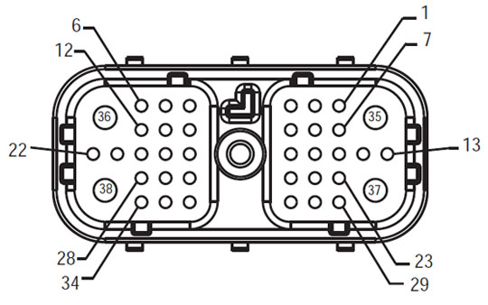
Uidheaman-eich Front View
(TECU – System Interface ceanglaiche)
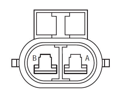
Uidheaman-eich Front View
(Rèile Tagh Motor
NOTE: Coimheadaibh air an Eaton Hybrid pàirtean agus ceanglaiche Àite Àiteachan airson an ceanglaiche ann MY08 Systems
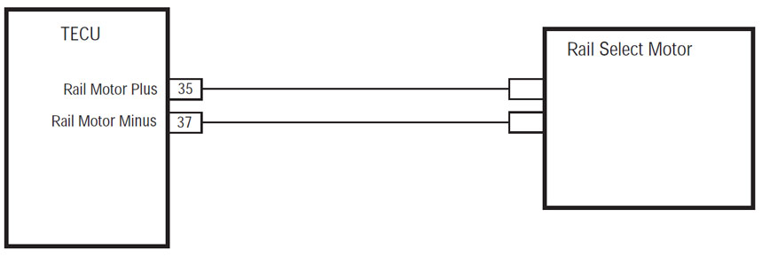
CHEUM 1.Verify leantainneachd Transmission Uidheaman-eich chuairtean.
- Fhaighinn air ais Gnìomhach coire còdan agus FMIs ServiceRanger le bhith a 'cleachdadh na 9 Way-Breithneachaidh ceanglaiche.
- prìomh dheth.
- Disconnect àicheil bataraidh càball.
- Dì-cheangail an Transmission Harness 38-Way Connector bhon TECU.
- Tomhais an aghaidh eadar na Transmission Uidheaman-eich 38 Way ceanglaiche Pin 35 agus Pin 37:
- Ma tha an aghaidh 0.3-150 ohms, a 'dol gu Ceum 2.
- Ma aghaidh tha taobh a-muigh de raon, a 'dol gu Ceum 3.
CHEUM 2. Dearbhaich leantainneachd Transmission Uidheaman-eich chuairtean a bhleith.
- Tomhais an aghaidh eadar na Transmission Uidheaman-eich 38 Way ceanglaiche Pin 35 agus talamh:
- Ma tha an aghaidh 10K ohms no barrachd, àite Transmission Electronic Control Aonad (TECU)(A-mhàin ma tha Sgàineadh a 'Chòd Gnìomhach), an uair sin a 'dol gu Ceum 4.
- Ma tha nas lugha na aghaidh 10K ohms, a 'dol gu Ceum 3.
CHEUM 3. Dearbhaich leantainneachd Rèile Tagh Motor Uidheaman-eich cuairt.
- Disconnect 2-Slighe Rèile Tagh Motor ceanglaiche bho Transmission Uidheaman-eich.
- Tomhais an aghaidh eadar Rèile Tagh Motor Uidheaman-eich 2-Way ceanglaiche Pin Pin A agus B agus A Pin a bhleith:
- Ma Pin aghaidh eadar A agus B Pin tha 0.3-150 ohms agus Pin A gu talamh 10K ohms no barrachd, àite Transmission Uidheaman-eich, an uair sin a 'dol gu Ceum 4.
- Ma aghaidh tha taobh a-muigh de raon, àite Electric Shifter, an uair sin a 'dol gu Ceum 4.
CHEUM 4. Dearbhaich càradh.
- prìomh dheth.
- Connectors a h-uile ath-cheangal agus an droch bhataraidh càball.
- prìomh air.
- còdan soilleir, fhaicinn Soilleir tàmh sgàinidhean.
- Stiùir an càr agus a 'feuchainn ri ath-shuidheachadh an còd.
- Lorg airson còdan, fhaicinn Faic dèanadach agus neo-ghnìomhach sgàinidhean.
- Ma eil còdan, deuchainn crìochnaichte.
- Ma coire Code 61 a rèir coltais, mearachd a lorg ann an deuchainnean, a 'dol gu Ceum 1.
- Ma tha an còd eile seach 61 a rèir coltais, fhaicinn Sgàineadh Code clàr-innse Clàr-.
na Sìde & rabhadh
Danger: Danger sealltainn bidh thu a dhroch leòn no a mharbhadh ma nach eil a 'leantainn modh comharraichte.
rabhadh: Rabhadh sealltainn an cunnart grad, a dh'fhaodadh a thoradh ann an droch leòn pearsanta mura bheil thu a 'leantainn modh-obrach a chomharrachadh.
Rabhaidh: Rabhaidh a 'sealltainn càr no seilbh milleadh dh'fhaodadh tachairt mura bheil thu a' leantainn modh-obrach a chomharrachadh.
Nota: Cuimhnich a 'sealltainn fiosrachadh a bharrachd a bhios a' cuideachadh ann an breithneachadh no càradh de phàirt / siostam.
Lean na modhan-obrach a shònrachadh ann an comharraichte òrdugh a sheachnadh leòn pearsanta:
1. Ma tha an bholtaids àrd-durcain a tha timcheall air a 'charbad agus an lockout tha air a stàladh air a' PEC, an t-aon neach a bu chòir cead a bhith a 'tòiseachadh a' charbad an neach a chuir an ainm ri lockout tag.
2. Mus ag obair air carbad no a 'fàgail chab fhad' sa bha an t-einnsean a 'ruith, bu chòir dhuibh a chur an gluasad luamhan ann an "N" a 'suidheachadh an pàirceadh bhris, agus bacadh a cuibhlichean.
3. Airson adhbharan sàbhailteachd, an-còmhnaidh a 'dol an sàs an t-seirbheis breicichean ron taghadh gear dreuchdan à "N."
4. Mus tòisich carbad-còmhnaidh a bhith nan suidhe ann an suidheachan aig an dràibhear, tagh "N" air a 'gluasad smachd, agus chuir a 'pàirceadh breicichean.
5. Ann an carbadan le ePTO, an t-einnsean agus / no
Motor / Generator a 'tòiseachadh ann an ePTO modh. Never 'cluich sam bith cumail suas no ag obair air a' chàir, fhad 'sa bha ann am modh seo.
6. 12-Volt Battery deimhinneach (+) agus àicheil (-) feumar a bhith glè ron sam bith tàthaidh air carbad sam bith a Hybrid uidheamaichte.
Rabhaidh: Lean na modhan-obrach a shònrachadh ann an comharraichte òrdugh a sheachnadh uidheam malfunction no milleadh.
Rabhaidh: Chan eil an leigeil mu sgaoil pàirceadh bhris no feuchainn a thaghadh gear gus an bruthadh èadhair a tha aig an ìre cheart.
Rabhaidh: Airson cron a sheachnadh ri sgaoileadh aig àm a tòbhadh an àite gluasad luamhan ann an "n" agus tog an iomairt cuibhlichean far na talmhainn no dì an driveline.
Àrd-bholtaids Sìde & rabhadh
- Cleachd CO2 no tioram Chemical innealan-smàlaidh.
- Tha an àrd-uèirichean bholtaids a tha air a chòmhdach ann an orains blàthachaidh no convoluted tubing agus comharraichte le rabhadh bileagan aig connectors.
- All Eaton® Hybrid Diesel / Electric carbadan a thèid a chomharrachadh 'Hybrid’ air an taobh a-muigh a 'chàir, còmhla ris a 'gluasad bileag air an dash.
- Coimheadaibh air OEM airson sònraichte location de chassis muin dà-chonnaidh phàirtean.
- Chan eil an gearradh ann an orains bholtaids àrd-càbaill.
- Chan eil gearradh a-steach no fosgail PEC.
- Chan eil gearradh a-steach no fosgail DC / DC Converter.
- Chan eil gearradh a-steach no fosgail Inverter.
A sòn bufair feumar a stèidheachadh agus àrd-bholtaids a chòmhdach miotagan rubair (clas 0 le leathar-dìon) Tha feum air ro-làimh a bhith ag obair air àrd-bholtaids. Mura lean an stiùireadh seo, dh'fhaodadh a dhroch leòn pearsanta no bàs.
Tha rubair a chòmhdach miotagan a dh'fheumas a bhith air caitheamh fhad 'sa bha ag obair air an bholtaids àrd-siostam a tha a' chlas 0 le leathar-dìon. Tha miotagan rubair bu chòir deuchainn ron h-uile a leanas a 'cleachdadh còmhdach-blàthachaidh miotagan rubair deuchainnean modh-obrach a gheibhear ann an "Breithneachaidh Innealan / Seirbheis Foillseachaidhean" air duilleag 6. Mura lean an stiùireadh seo, dh'fhaodadh a dhroch leòn pearsanta no bàs.
Mus sgrùdadh no ag obair sam bith air bholtaids àrd-càbaill no co-phàirtean an "Àrd-bholtaids Seirbheis Shutdown agus Cumhachd-Up Modh-obrach" air duilleag 4 bu chòir a leantainn. Mura lean an stiùireadh seo, dh'fhaodadh a dhroch leòn pearsanta no bàs.
Tha Lockout agus Tagout innealan Cha bu chòir a thoirt air falbh leis an teicneolaiche a chur an Lockout agus Tagout innealan air an càr. Mura lean an stiùireadh seo, dh'fhaodadh a dhroch leòn pearsanta no bàs.
Àrd-bholtaids a chòmhdach miotagan rubair (clas 0 le leathar-dìon) Feumar nuair a bh'air a bhith ag obair sam bith air a '
bholtaids àrd-càbaill. The "Àrd-bholtaids Seirbheis Shutdown agus Cumhachd-Up Modh-obrach" air duilleag 4 Feumar leantainn mus deach a thoirt air falbh sam bith bholtaids àrd-càbaill. Mura lean an stiùireadh seo, dh'fhaodadh a dhroch leòn pearsanta no bàs.
Àrd-bholtaids càbaill is uèirichean tha orains agus tha rabhadh bileag aig a 'connectors. Àrd-bholtaids co-phàirtean a tha comharraichte le bileag. Àrd-bholtaids a chòmhdach miotagan rubair (clas 0 le leathar-dìon) Feumaidh a chleachdadh nuair a tha ag obair air gin de na co-phàirtean. Mura lean an stiùireadh seo, dh'fhaodadh a dhroch leòn pearsanta no bàs.
Àrd-bholtaids Seirbheis Shutdown Dòighean-obrach
 1. Follow "Àrd-bholtaids Obair Sgìre" modh.
2. Locate an dearg PEC Seirbheis Switch air beulaibh na PEC agus a phutadh chur dheth.
3. Thoir air falbh an t-Seirbheis Switch Cover is a stàladh an Lockout camagan (J48506).
4. Tag cuireadh gu Lockout camagan.
5. Dèanamh cinnteach gum PEC Seirbheis Switch nach urrainn gluasad bho far an suidheachadh.
6. Leig an t-siostam a chaidh a shuidheachadh airson a 'char as lugha 5 mionaid a leigeil bholtaids àrd.
7. Ceangail ServiceRanger agus faic Dàta Monitor PID 116 ris an cante "Àrd-bholtaids Battery Comais." chleachdadh SPN 520323 airson J1939 ceangal "Battery bholtaids RB" (Relay Box).
8. Tha an bholtaids a bu chòir a bhith 30 volts no nas lugha. Ma tha an bholtaids a tha os cionn 30 volts, Chan eil obair air a 'charbad agus fios Eaton® aig 1-800-826-COBHAIR (4357).
9. Tionndaidh Ignition key dheth agus a dhol air adhart a chàradh no troubleshooting cheum.
Nota: Tha an bholtaids a 'tuiteam gu neoni nuair a tha na prìomh dheth.
Àrd-bholtaids Seirbheis Cumhachd-Up Modh-obrach
1. Stàlaich h-uile àrd-bholtaids connectors a-steach glaiste dreuchdan aca.
2. Ma tha thu an neach a tha ag obair air a 'charbaid, a thoirt air falbh Lockout camagan agus tag.
3. Reinstall an Lockout camagan thairis air an t-Seirbheis Switch.
4. Pull an t-Seirbheis Switch-mach agus leig carbad seata airson 2 mionaid.
5. Start càr nuair a bhios iomchaidh.
Eaton Hybrid pàirtean agus ceanglaiche Àite

Eaton Hybrid pàirtean agus ceanglaiche Àite MY09 Systems

sam bith sgaoilidh phàirt feumaidh tu feumaidh sinn e! Aon latha luingeis ri fhaotainn, an t-saoghail.
FEUMAIDH taic an-asgaidh bho aon de ar n-eòlaichean?