Eaton Fuller przekładnia hybrydowa kod usterki 53 – Konwerter DC / DC
Kod błędu dla Eaton modeli hybrydowych układów napędowych (MY08) EH 8E306A-U, EH-8E306A-UPG, EH-8E306A-UP, EH-8E306A-CD, EH-8E306A-T, EH-6E606B-CD, (MY09) EH 8E406A-E / P, EH-8E406A-UP, EH-8E406A-UPG, EH-8E406A-CD, EH-8E406A-CDG, EH-8E406A-CDR, EH-8E406A-T, EH-6E706B-CD, EH-6E706B-P i EH-6E706B-UPG. Przeczytaj poniżej, aby dowiedzieć się, jak testować, wyczyścić i naprawić błędy kod błędu dla Freightliner, Mack, Peterbilt, Kenworth, Volvo ciężarówka i Międzynarodowy. Konwerter DC / DC jest podłączony do wysokiego napięcia Power Electronics Carrier (PEC), który zapewnia 340 V DC. Napięcie jest zszedł do 12-V DC i używane do utrzymania układu 12 V podczas pracy silnika wyłączyć WOM. DC / DC utrzymuje stały 12.6 volt wyjście i zwiększa natężenie z zapotrzebowaniem pojazdu do 1.5 kW lub 120 ampery.
Kod błędu 53 – DC/DC Converter Detection
Następujące warunki muszą być spełnione, zanim system wykryje usterkę:
- HCM napięcie zapłonu jest większa niż 7 wolt i niższego 16 woltów.
Uwaga: Podczas rozwiązywania kod Nieaktywne odnoszą się do Tryb diagnostyczny produktu (PDM)
Ustaw warunki do aktywnego kodu usterki
- MFW 12 i FMI 14 ustawić dla następujących powodów:
- Spadek napięcia pojazdu jest większa niż 0.7 volts at the start of ePTO mode.
- Vehicle battery voltage is equal to or less than 11.3 woltów.
- If there is no converter to battery cable fault, power drop across the converter is less than 900 watów (MFW 12), or power drop across the converter is greater than 1500 watów (MFW 14).
Awaryjna, gdy kod usterki 53 jest ustawiony wystąpić następujące warunki:
• Amber „Check Hybrid” światło świeci.
• Usterka zostaje zapisana w module sterującym hybrydowego (HCM) pamięć.
• HCM wymaga silnik do napędu WOM i utrzymania systemu 12-woltowy.
Ustaw warunki do błędu kod nieaktywny
Tylko Nieaktywne błędy mogą zostać usunięte z Electronic Control Transmission Unit (TECU) Historia HCM lub używając ServiceRanger. TECU automatycznie usuwa usterki z historii po 200 godziny i HCM automatycznie usuwa usterki z historii po winy jest nieaktywna 200 godziny.
Ten kod błędu może być spowodowane przez jedną z następujących czynności::
- MFW 12
- Konwerter DC / DC
- MFW 14
- obciążenie pojazdu jest powyżej maksimum 1.5 kw output of the converter.
Kod błędu 53 – DC/DC Converter Test
Component System Identification MY09:
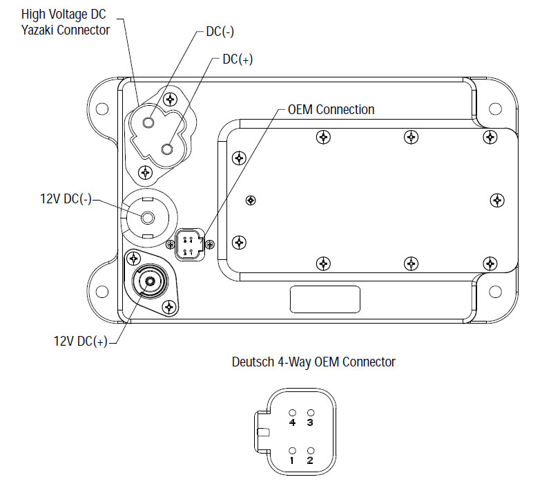
Konwerter DC / DC
1. Top: DC ujemny (-); Dolny: DC dodatni (+)
2. 12-V DC ujemny (-)
3. 12-V DC dodatni (+)
4. połączenie OEM
5. Porty chłodzące
UWAGA: Odnoszą się do Eaton Hybrid i lokalizacja złącza komponentowego dla złączy w MY08 Systems
UWAGA: Odnoszą się do Eaton Hybrid i lokalizacja złącza komponentowego dla złączy w MY09 Systems.
ostrzeżenia &wzmacniacz; Przestrogi
Zagrożenie: Niebezpieczeństwo wskazuje zostaniesz poważnie ranny lub zabity, jeśli nie postępować zgodnie z procedurą wskazaną.
Ostrzeżenie: Ostrzeżenie wskazuje na bezpośrednie zagrożenie, które mogłyby doprowadzić do poważnych obrażeń, jeśli nie postępować zgodnie z procedurą wskazaną.
Uwaga: Ostrzeżenie wskazuje pojazdu lub uszkodzenia mienia może nastąpić, jeśli nie postępować zgodnie z procedurą wskazaną.
Uwaga: Uwaga wskazuje dodatkowe szczegóły, które pomogą w diagnozie lub naprawy systemu komponentowego /.
Postępuj według określonych procedur w podanej kolejności, aby uniknąć zranienia:
1. Jeśli stożki wysokiego napięcia są wokół pojazdu, a blokada jest zainstalowany na PEC, jedyną osobą, która powinna mieć możliwość uruchomienia pojazdu jest osoba, która podpisała znacznik blokady.
2. Przed rozpoczęciem pracy w pojeździe lub opuszczania kabiny, gdy silnik jest uruchomiony, należy ustawić dźwignię zmiany biegów w „N” zaciągnąć hamulec postojowy, i zablokować koła.
3. Z powodów bezpieczeństwa, zawsze angażować hamulców przed wybraniu pozycji biegów od „N.”
4. Przed uruchomieniem pojazdu należy zawsze siedzącej w fotelu kierowcy, wybierz „N” w sprawie kontroli zmianowym, i ustawić hamulce postojowe.
5. W przypadku pojazdów z EPTO, silnik i / lub
Silnik / generator można uruchomić w trybie EPTO. Nigdy nie wykonywać żadnych prac konserwacyjnych lub na pojeździe, w tym trybie.
6. 12-Volt Battery pozytywny (+) i negatywne (-) musi być odłączony przed jakimkolwiek spawania na każdym Hybrid wyposażony pojazd.
Uwaga: Postępuj według określonych procedur w podanej kolejności, aby uniknąć uszkodzenia sprzętu lub obrażenia.
Uwaga: Nie zwolnić hamulec postojowy lub próbować wybrać bieg, aż ciśnienie powietrza jest na właściwym poziomie.
Uwaga: Aby uniknąć uszkodzenia przekładni podczas holowania ustawić dźwignię zmiany biegów w „n” i unieść koła napędowe z ziemi lub odłączyć układ napędowy.
Ostrzeżenia wysokiego napięcia & Przestrogi
- Używać CO2 lub suche chemiczne Gaśnice.
- Przewody wysokiego napięcia jest pokryta izolacją w kolorze pomarańczowym lub pokrętny rurek i oznaczone etykietami ostrzegawczymi na złączach.
- Wszystkie Eaton® hybrydowy diesel / Pojazdy elektryczne będą oznaczone „Hybrid’ na zewnątrz pojazdu, wraz z etykietą zmianowym na desce rozdzielczej.
- Patrz OEM dla określonego położenia podwozia zamontowane komponentów hybrydowych.
- NIE pokroić pomarańczowych przewodów wysokiego napięcia.
- NIE pokroić lub otworzyć PEC.
- NIE pokroić lub otworzyć konwerter DC / DC.
- NIE pokroić lub otworzyć falownik.
Strefa buforowa musi być ustawiony i wysokiego napięcia z izolacją rękawice gumowe (klasa 0 ze skórzanymi ochraniaczami) są wymagane przed pracuje na wysokim napięciu. Niezastosowanie się do tych zaleceń może doprowadzić do poważnych obrażeń lub śmierci.
Rękawice gumowe-izolacyjne, które należy nosić podczas pracy przy instalacji wysokiego napięcia są klasą 0 ze skórzanymi ochraniaczami. Rękawice gumowe powinny być badane przed każdym użyciem, zgodnie z procedurą gumowe rękawice izolacyjne testowania znaleźć w „Narzędzia diagnostyczne / publikacje serwisowe” na stronie 6. Niezastosowanie się do tych zaleceń może doprowadzić do poważnych obrażeń lub śmierci.
Przed sprawdzeniem lub pracujących na wszelkich przewodów lub elementów wysokiego napięcia z „High-Voltage Shutdown Obsługa i Power-Up procedury” na stronie 4 powinny być przestrzegane. Niezastosowanie się do tych zaleceń może doprowadzić do poważnych obrażeń lub śmierci.
Urządzenia Lockout i Tagout powinna być usunięta tylko przez technika, który umieszczony urządzeń Lockout i Tagout na pojeździe. Niezastosowanie się do tych zaleceń może doprowadzić do poważnych obrażeń lub śmierci.
Wysokiego napięcia izolowane rękawice gumowe (klasa 0 ze skórzanymi ochraniaczami) należy nosić podczas pracy na dowolny
Kable wysokiego napięcia. „High-Voltage Shutdown Obsługa i Power-Up Procedura” na stronie 4 Należy następnie przed usuwania kabli wysokiego napięcia. Niezastosowanie się do tych zaleceń może doprowadzić do poważnych obrażeń lub śmierci.
Kable wysokiego napięcia i przewody są pomarańczowe i zawierają tabliczkę ostrzegawczą na złączach. elementy wysokonapięciowe są oznaczone etykietą. Wysokiego napięcia izolowane rękawice gumowe (klasa 0 ze skórzanymi ochraniaczami) muszą być stosowane podczas pracy na którykolwiek z tych składników. Niezastosowanie się do tych zaleceń może doprowadzić do poważnych obrażeń lub śmierci.
Wysokiego napięcia wyłączenia usługi Procedury
 1. Postępuj zgodnie z „High-Voltage Obszar roboczy” procedura.
2. Zlokalizuj czerwony przełącznik PEC serwisowa w przedniej części PEC i wcisnąć wyłączyć.
3. Zdejmij pokrywę wyłącznik serwisowy i zainstalować wspornik Lockout (J48506).
4. Zapiąć tag Blokada Wspornik.
5. Upewnić się, że przełącznik PEC usługa nie może przejść z pozycji wyłączonej.
6. Aby system mógł ustawić na minimum 5 minuty do rozładowania wysokim napięciem.
7. Podłączyć ServiceRanger i wyświetlić dane monitorowania PID 116 zwane „High-Voltage Potencjał akumulatora.” Use SPN 520323 połączenie J1939 „Napięcie akumulatora RB” (przekaźnik Box).
8. Napięcie powinno być 30 V lub mniej. Jeśli napięcie jest powyżej 30 woltów, nie działają na pojeździe i skontaktować Eaton® na 1-800-826-HELP (4357).
9. Obrócić kluczyk wyłączyć i przystąpić do naprawy lub etap rozwiązywania problemów.
Uwaga: Napięcie spada do zera, gdy klucz jest wyłączony.
Procedura wysokiego napięcia obsługa Power-Up
1. Zainstalować wszystkie złącza wysokiego napięcia w ich położeniach zamkniętych.
2. Jeśli jesteś osobą pracującą na pojeździe, usunąć blokadę wspornika i tag.
3. Ponownie zainstaluj Blokada Wspornik nad wyłącznik serwisowy.
4. Pociągnąć Switch Service i pozwól zestaw dla pojazdów 2 minuty.
5. Zacznij pojazdu w razie potrzeby.
Eaton Hybrid i lokalizacja złącza komponentowego

Eaton Hybrid Komponent i lokalizacja Złącze MY09 Systems

KROK 1. Zweryfikować stan kodu błędu aktywnych i nieaktywnych.
- Oceń i wykonaj ostrzeżenia & Przestrogi.
- Odzyskaj Aktywne kody błędów i FMIs z ServiceRanger użyciu złącze diagnostyczne 9-Way.
- Key off.
- Odłącz złącze czujnika temperatury na silniku / prądnicy.
Zagrożenie: Widzieć Wysokiego napięcia wyłączania zasilania-Serwis i procedur. Postępuj zgodnie z procedurami, aby uniknąć porażenia prądem, spalić lub śmierci z niewłaściwym wysokiego napięcia. - Które są obecne FMIs?
- Jeśli FMI 12 znajduje się na liście, wymienić konwerter DC / DC, Następnie przejdź do kroku 2.
- Jeśli FMI 14 znajduje się na liście, popyt pojazdu 12 V przekracza pojemność przetwornicy DC / DC. Ładunki powinny być usunięte z układu 12 V, aby utrzymać maksymalną 1.5 kW Całkowite zużycie.
KROK 2. zweryfikować naprawy.
- Key off.
- Podłącz wszystkie złącza i ujemny przewód akumulatora.
- na klucz.
- kasowanie kodów, widzieć Pogodne Nieaktywne Usterki.
- Kierowania pojazdem i próba zresetowania kodu.
- Sprawdzić kody, widzieć Zobacz Usterki aktywnych i nieaktywnych.
- Jeśli nie ma kodów, test jest kompletny.
- Jeśli kod błędu 53 pojawia się, znaleźć błąd w testowaniu, przejdź do kroku 1.
- Jeśli kod inny niż 53 pojawia się, widzieć Lista błędów Kod Index.
Każdy część transmisji trzeba ją mamy! Tego samego dnia wysyłki dostępne, na calym swiecie.
POTRZEBUJESZ darmowe wsparcie ze strony jednego z naszych ekspertów?