ईटन फुलर हाइब्रिड ट्रांसमिशन फॉल्ट कोड 47 – J1939 एबीएस संदेश (HCM)
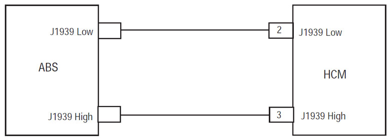
ईटन हाइब्रिड ड्राइव सिस्टम मॉडल के लिए कोड दोष (MY08) एह-8E306A-यू, EH-8E306A-UPG, एह-8E306A उत्तर प्रदेश, EH-8E306A-CD, EH-8E306A-T और EH-6E606B-CD. परीक्षण करने के लिए कैसे जानने के लिए नीचे पढ़ें, साफ़ करें और अपने Freightliner के लिए गलती कोड त्रुटियों को ठीक, मैक, Peterbilt, Kenworth, वोल्वो और अंतर्राष्ट्रीय ट्रक. J1939 एक के साथ एक उच्च गति मुड़ जोड़ी 250K डेटा लिंक है 120 लिंक के हर कोने पर ओम बाधा. HCM 38-वे कनेक्टर पर J1939 डेटा लिंक से जुड़ा है. इस कड़ी HCM को सूचना प्रसारित और इस तरह के एंटी-लॉक ब्रेकिंग सिस्टम के रूप में नेटवर्क पर अन्य मॉड्यूल के साथ संवाद करने के लिए प्रयोग किया जाता है (एबीएस) मॉड्यूल.
फाल्ट कोड 47 – J1939 एबीएस संदेश (HCM) खोज
इससे पहले कि प्रणाली गलती का पता लगाता है निम्नलिखित पूर्व शर्त पूरी होनी चाहिए:
- HCM प्रज्वलन वोल्टेज से अधिक है 7 वोल्ट और कम से कम 16 वोल्ट.
- J1939 डेटा लिंक संचार गलती निष्क्रिय है.
ध्यान दें: जब एक निष्क्रिय कोड समस्या निवारण को देखें उत्पाद नैदानिक मोड (PDM)
स्थितियां फॉल्ट कोड सक्रिय सेट करने के लिए
- एमआई 9 सेट किया गया है जब HCM एबीएस संदेश के लिए "एंटी-लॉक ब्रेक लगाना सक्रिय" प्राप्त करने के लिए विफल रहता है 30 लगातार संदेशों या अधिक से अधिक, यह J1939 पर अन्य मॉड्यूल के साथ संवाद स्थापित करने के लिए जारी है, जबकि.
- अंतर्राष्ट्रीय मुद्रा कोष 14 सेट किया गया है जब HCM एबीएस मॉड्यूल से आने वाले संदेशों का पता लगाता है; हालाँकि, "एंटी-लॉकिंग ब्रेकिंग एक्टिव" संदेश त्रुटि के रूप में प्राप्त होता है या उपलब्ध नहीं है.
निवर्तन जब दोष कोड 47 सेट किया गया है निम्न स्थितियों में पाए जाते हैं:
- एम्बर "चेक हाइब्रिड" प्रकाश illuminates.
- दोष हाइब्रिड कंट्रोल मॉड्यूल में संग्रहित है (HCM) याद.
- दोष होता है, जबकि आगे बढ़ तो, आपरेशन AutoShift केवल मोड में चला जाता.
- इलेक्ट्रिक मोटर / जनरेटर असिस्ट और पुनर्जनन अक्षम हैं; हालाँकि, उच्च वोल्टेज रिले संचालित रहने.
- ट्रांसमिशन चूक 1 करने के लिए गियर शुरू.
स्थितियां फॉल्ट कोड निष्क्रिय सेट करने के लिए
केवल निष्क्रिय दोष ट्रांसमिशन इलेक्ट्रॉनिक कंट्रोल यूनिट से साफ किया जा सकता (TECU) या HCM इतिहास ServiceRanger का उपयोग कर. TECU बाद स्वचालित रूप से इतिहास से दोष को साफ करता है 200 घंटे और HCM स्वचालित रूप से गलती के बाद इतिहास से दोष को साफ करता है के लिए निष्क्रिय कर दिया गया है 200 घंटे.
यह गलती कोड निम्न में से कोई कारण हो सकता है:
- अंतर्राष्ट्रीय मुद्रा कोष 9
- J1939 डेटा लिंक
- एबीएस मॉड्यूल
- अंतर्राष्ट्रीय मुद्रा कोष 14
- एबीएस मॉड्यूल J1939 के बजाय J1708 या अनुरूप पर बातचीत करने के लिए कॉन्फ़िगर किया गया.
- एबीएस मॉड्यूल
फाल्ट कोड 47 – J1939 एबीएस संदेश (HCM) परीक्षा
घटक पहचान:
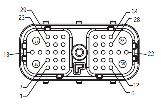
मोर्चा हार्नेस देखें
(HCM – वाहन इंटरफ़ेस कनेक्टर)
ध्यान दें: को देखें ईटन हाइब्रिड घटक और कनेक्टर स्थान कनेक्टर स्थान के लिए
चेतावनी &एम्प; चेतावनी
खतरा: खतरे को इंगित करता है कि आप गंभीर रूप से घायल कर दिया जाएगा या मार डाला है, तो संकेत प्रक्रिया का पालन नहीं करते.
चेतावनी: चेतावनी एक तत्काल खतरा इंगित करता है, गंभीर व्यक्तिगत चोट में परिणाम सकता है जो यदि आपने दर्शाया प्रक्रिया का पालन नहीं करते.
सावधान: सावधानी इंगित करता है वाहन या संपत्ति के नुकसान हो सकता है यदि आपने दर्शाया प्रक्रिया का पालन नहीं करते.
ध्यान दें: नोट अतिरिक्त विस्तार है कि निदान या एक घटक / प्रणाली की मरम्मत में सहायता करेगा इंगित करता है.
इंगित आदेश व्यक्तिगत चोट से बचने के लिए निर्दिष्ट प्रक्रियाओं का पालन करें:
1. उच्च वोल्टेज शंकु वाहन के आसपास हैं और तालाबंदी पीईसी पर स्थापित है, केवल एक ही व्यक्ति है कि वाहन शुरू करने के लिए अनुमति दी जानी चाहिए जो व्यक्ति तालाबंदी टैग पर हस्ताक्षर किए है.
2. एक वाहन पर काम कर रहा है या टैक्सी से निकलने से पहले इंजन चल रहा है, जबकि, आप "एन" में शिफ्ट लीवर रखूं पार्किंग ब्रेक सेट, और पहियों ब्लॉक.
3. सुरक्षा कारणों की वजह से, हमेशा सेवा ब्रेक संलग्न "एन" से गियर पदों का चयन करने से पहले
4. इससे पहले कि करियर की शुरुआत एक वाहन हमेशा चालक की सीट में बैठा, चयन "एन" पारी नियंत्रण पर, और पार्किंग ब्रेक सेट.
5. ePTO साथ वाहनों में, इंजन और / या
मोटर / जनरेटर ePTO मोड में शुरू कर सकते हैं. कभी किसी रखरखाव या वाहन पर काम, इस मोड में, जबकि.
6. 12-वोल्ट की बैटरी सकारात्मक (+) और नकारात्मक (-) किसी भी हाइब्रिड सुसज्जित वाहन पर किसी भी वेल्डिंग से पहले काट दिया जाना चाहिए.
सावधान: इंगित आदेश उपकरण की खराबी या क्षति से बचने के लिए निर्दिष्ट प्रक्रियाओं का पालन करें.
सावधान: पार्किंग ब्रेक रिलीज या जब तक हवा के दबाव सही स्तर पर है एक गियर का चयन करने का प्रयास न करें.
सावधान: रस्सा जगह के दौरान "एन" में शिफ्ट लीवर संचरण को क्षति से बचाने और जमीन से ड्राइव पहियों लिफ्ट या driveline डिस्कनेक्ट करने के लिए.
उच्च वोल्टेज चेतावनी & चेतावनी
- सीओ 2 या सूखी रासायनिक अग्निशामक का प्रयोग करें.
- उच्च वोल्टेज तारों नारंगी इन्सुलेशन या जटिल ट्यूबिंग में शामिल और कनेक्टर्स पर चेतावनी लेबल के साथ चिह्नित है.
- सभी Eaton® हाइब्रिड डीजल / इलेक्ट्रिक वाहनों में चिह्नित किया जाएगा 'हाइब्रिड’ वाहन के बाहर की दुनिया में, पानी का छींटा पर पारी लेबल के साथ.
- चेसिस घुड़सवार संकर घटकों के विशिष्ट स्थान के लिए OEM का संदर्भ लें.
- नारंगी उच्च वोल्टेज केबल में कटौती नहीं करते हैं.
- में कटौती या न खोलें पीईसी.
- में कटौती या डीसी / डीसी कनवर्टर न खोलें.
- में कटौती या इन्वर्टर न खोलें.
एक बफर जोन स्थापित किया जाना चाहिए और उच्च वोल्टेज रबर के दस्ताने अछूता (कक्षा 0 चमड़े के संरक्षक के साथ) उच्च वोल्टेज पर काम करने से पहले आवश्यक हैं. विफलता इन निर्देशों का पालन करने के लिए गंभीर व्यक्तिगत चोट या मृत्यु में हो सकता है.
रबर अछूता दस्ताने है कि जब तक उच्च वोल्टेज प्रणाली पर काम कर रहा पहनना आवश्यक वर्ग के हैं 0 चमड़े के संरक्षक के साथ. रबर के दस्ताने रबर इन्सुलेशन दस्ताने परीक्षण प्रक्रिया पृष्ठ पर "निदान के औजार / सेवा प्रकाशन" में पाया निम्नलिखित हर उपयोग करने से पहले परीक्षण किया जाना चाहिए 6. विफलता इन निर्देशों का पालन करने के लिए गंभीर व्यक्तिगत चोट या मृत्यु में हो सकता है.
पृष्ठ पर निरीक्षण या किसी उच्च वोल्टेज केबल या घटकों पर काम कर "उच्च वोल्टेज सेवा बंद और पावर-अप प्रक्रिया" इससे पहले 4 पालन किया जाना चाहिए. विफलता इन निर्देशों का पालन करने के लिए गंभीर व्यक्तिगत चोट या मृत्यु में हो सकता है.
तालाबंदी और Tagout उपकरणों केवल तकनीशियन है कि वाहन पर तालाबंदी और Tagout उपकरणों रखा द्वारा हटा दिया जाना चाहिए. विफलता इन निर्देशों का पालन करने के लिए गंभीर व्यक्तिगत चोट या मृत्यु में हो सकता है.
उच्च वोल्टेज रबर अछूता दस्ताने (कक्षा 0 चमड़े के संरक्षक के साथ) जब किसी भी पर काम कर पहनना आवश्यक है
उच्च वोल्टेज केबल. "उच्च वोल्टेज सेवा बंद और पावर-अप प्रक्रिया" पृष्ठ पर 4 किसी भी उच्च वोल्टेज केबल को हटाने से पहले पालन किया जाना चाहिए. विफलता इन निर्देशों का पालन करने के लिए गंभीर व्यक्तिगत चोट या मृत्यु में हो सकता है.
उच्च वोल्टेज केबल और तारों नारंगी हैं और कनेक्टर्स पर एक चेतावनी लेबल होना. उच्च वोल्टेज घटकों एक लेबल के साथ चिह्नित हैं. उच्च वोल्टेज रबर अछूता दस्ताने (कक्षा 0 चमड़े के संरक्षक के साथ) जब इन घटकों में से किसी पर काम कर इस्तेमाल किया जाना चाहिए. विफलता इन निर्देशों का पालन करने के लिए गंभीर व्यक्तिगत चोट या मृत्यु में हो सकता है.
उच्च वोल्टेज सेवा शटडाउन प्रक्रिया
 1. का पालन करें "उच्च वोल्टेज कार्य क्षेत्र" प्रक्रिया.
2. पीईसी के मोर्चे पर लाल पीईसी सेवा स्विच का पता लगाएं और धक्का बंद.
3. सेवा स्विच कवर निकालें और तालाबंदी ब्रैकेट स्थापित (J48506).
4. तालाबंदी ब्रैकेट को जकड़ना टैग.
5. पीईसी सेवा स्विच सुनिश्चित गलत स्थान से स्थानांतरित नहीं कर सकते.
6. प्रणाली की एक न्यूनतम के लिए निर्धारित करने की अनुमति 5 मिनट उच्च वोल्टेज का निर्वहन करने के.
7. ServiceRanger कनेक्ट और देखने डाटा मॉनिटर पीआईडी 116 कहा जाता है "उच्च वोल्टेज बैटरी क्षमता।" SPN उपयोग 520323 J1939 कनेक्शन के लिए "बैटरी वोल्टेज आरबी" (रिले बॉक्स).
8. वोल्टेज होना चाहिए 30 वोल्ट या कम. अगर वोल्टेज से ऊपर है 30 वोल्ट, वाहन पर काम नहीं करते और 1-800-826-HELP पर Eaton® संपर्क (4357).
9. इग्निशन चाभी को बंद करें और मरम्मत या चरण समस्या निवारण के लिए आगे बढ़ें.
ध्यान दें: वोल्टेज शून्य जब कुंजी बंद है चला जाता है.
उच्च वोल्टेज सेवा पावर-अप प्रक्रिया
1. उनके बंद कर दिया स्थिति में सभी उच्च वोल्टेज कनेक्टर्स स्थापित करें.
2. व्यक्ति वाहन पर काम कर रहे हैं, तो आप, तालाबंदी ब्रैकेट और टैग को निकालने.
3. सेवा स्विच से अधिक तालाबंदी ब्रैकेट पुनर्स्थापित करें.
4. सेवा खींचो बाहर स्विच और के लिए वाहन सेट करते हैं 2 मिनट.
5. वाहन शुरू जब उचित.
ईटन हाइब्रिड घटक और कनेक्टर स्थान

ईटन हाइब्रिड घटक और कनेक्टर स्थान MY09 सिस्टम्स

कदम 1. सक्रिय और निष्क्रिय गलती कोड की स्थिति और वर्तमान FMIs सत्यापित करें.
- 9-वे निदान कनेक्टर का उपयोग कर ServiceRanger के साथ सक्रिय गलती कोड और FMIs पुन: प्राप्त करें.
- कौन सा FMIs मौजूद हैं?
- फॉल्ट कोड हैं 47 अंतर्राष्ट्रीय मुद्रा कोष 9 सूचिबद्ध है, चिंता या तो एबीएस मॉड्यूल या एबीएस मॉड्यूल से जे1939 डेटा लिंक बैकबोन तक जे1939 डेटा लिंक को लेकर है. मरम्मत प्रक्रियाओं के लिए OEM का संदर्भ लें.
- फॉल्ट कोड हैं 47 अंतर्राष्ट्रीय मुद्रा कोष 14 सूचिबद्ध है, चिंता एबीएस मॉड्यूल J1939 संचार के बजाय J1708 के लिए कॉन्फ़िगर किया जा रहा है, या एबीएस मॉड्यूल के साथ. मरम्मत प्रक्रियाओं के लिए OEM का संदर्भ लें.
कोई भी संचरण हिस्सा आप हमारे पास है जरूरत! उसी दिन शिपिंग उपलब्ध, दुनिया भर.
हमारे विशेषज्ञों में से एक से निःशुल्क सहायता की जरूरत?