ایتون فولر ترکیبی کد خطا انتقال 38 – رله فن باتری
خطا کد برای ایتون ترکیبی مدل های سیستم درایو (MY08) EH-8E306A-U, EH-8E306A-UPG, EH-8E306A-UP, EH-8E306A-CD, EH-8E306A-T, EH-6E606B-CD, (MY09) EH-8E406A-U / P, EH-8E406A-UP, EH-8E406A-UPG, EH-8E406A-CD, EH-8E406A-CDG, EH-8E406A-CDR, EH-8E406A-T, EH-6E706B-CD, EH-6E706B-P و EH-6E706B-UPG. رله فن باتری به طور معمول انتقال باز متصل به ماژول کنترل ترکیبی (HCM) در سمت شاهد. هنگامی که قدرت HCM مدار کنترل, آن را می بندد تماس رله و تبدیل بر روی رله. قدرت باتری رله فن فن باتری واقع در برق الکترونیک حامل (PEC), خنک کننده باتری با ولتاژ بالا.
خطا کد 38 – تشخیص باتری رله فن
پیش شرط زیر باید رعایت شود قبل از سیستم تشخیص گسل:
- ولتاژ جرقه HCM بزرگتر از 7 ولت و کمتر از 16 ولت.
توجه داشته باشید: در هنگام عیب یابی کد غیر فعال به مراجعه محصولات حالت تشخیصی (PDM)
شرایط به تنظیم کد گسل فعال
شرایط به تنظیم گسل:
• صندوق بین المللی پول 3 قرار است که ولتاژ سنسور بزرگتر از است 4.1 ولت برای 10 ثانیه, در حالی که دمای اینورتر به پایان رسیده است 35 درجه سانتی گراد یا 95 ° F, و یا اگر ولتاژ خروجی سنسور کمتر از است 0.2 ولت برای 10 ثانیه.
جانشین هنگامی که کد خطا 38 قرار است شرایط زیر رخ می دهد:
- صندوق بین المللی پول 3 قرار است که HCM تشخیص کوتاه به باتری در مدار سیم پیچ از رله فن باتری.
- صندوق بین المللی پول 4 قرار است که HCM کوتاه به زمین در مدار سیم پیچ از رله فن باتری تشخیص.
- صندوق بین المللی پول 5 قرار است که HCM در مدار سیم پیچ از رله فن باتری باز را شناسایی.
- صندوق بین المللی پول 14 قرار است که شرایط زیر صادق هستند 10 دقایق:
- High-voltage battery temperature is greater than 131 ° F (55 ° C)
- تفاوت بین درجه حرارت حداقل و حداکثر باتری کمتر از است 33 ° F (1 ° C)
- هیچ گسل دمای باتری را از ماژول کنترل باتری
شرایط به تنظیم گسل کد غیر فعال
فقط گسل غیر فعال را می توان از واحد انتقال کنترل الکترونیکی پاک (TECU) و یا سابقه HCM با استفاده از ServiceRanger. TECU به طور خودکار پاک گسل از تاریخ، پس از 200 ساعت و HCM به طور خودکار پاک گسل از تاریخ پس از گسل است برای غیر فعال شده 200 ساعت ها.
این کد خطا را می توان با هر یک از موارد زیر ایجاد:
- صندوق بین المللی پول 3, 4, 5
- مهار خودرو از HCM به باتری رله فن
- رله فن باتری
- HCM
- صندوق بین المللی پول 14
- رله فن باتری
- باتری فن
- متصل فیلتر هوا
- باتری رله فن منبع تغذیه اصلی
خطا کد 38 – باتری فن تست رله
شناسایی اجزاء:
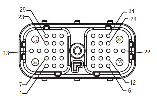
جبهه مهار نمایش
HCM – رابط Connecto ترکیبی سیستم
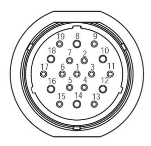
مهار اتصال نمایش
(PEC 19 – مسیر)
توجه داشته باشید: به مراجعه ایتون و اجزای ترکیبی و اتصال محل سکونت برای مکان های اتصال در سیستم MY08
توجه داشته باشید: به مراجعه ایتون و اجزای ترکیبی و اتصال محل سکونت برای مکان های اتصال در سیستم MY09.
هشدارها &آمپر; هشدار
خطر: خطر را نشان می دهد به شما خواهد شد به شدت مجروح و یا کشته اگر انجام این روش نشان داد پیروی نمی.
هشدار: هشدار نشان می دهد خطر فوری, که می تواند در آسیب شدید شخصی در نتیجه اگر شما انجام این روش نشان داد پیروی نمی.
احتیاط: توجه نشان می دهد خودرو یا خسارت می تواند رخ دهد اگر شما روش نشان داد پیروی نمی.
توجه داشته باشید: توجه نشان می دهد جزئیات اضافی که در تشخیص و یا تعمیر یک جزء / سیستم کمک خواهد کرد.
دنبال روش مشخص شده در جهت نشان داد برای جلوگیری از آسیب های شخصی:
1. اگر مخروط با ولتاژ بالا در سراسر وسیله نقلیه هستند و قفل بر روی PEC نصب, تنها کسی که باید اجازه داده شود برای شروع وسیله نقلیه شخصی که برچسب قفل امضا است.
2. قبل از کار بر روی یک وسیله نقلیه و یا خروج از کابین در حالی که موتور در حال اجرا است, شما باید دسته دنده در "N" قرار دهید مجموعه ترمز دستی, و جلوگیری از چرخ.
3. به دلایل ایمنی, همیشه درگیر ترمز خدمات قبل از انتخاب موقعیت دنده از "N"
4. قبل از شروع یک خودرو همیشه در صندلی راننده نشسته, را انتخاب کنید "N" در کنترل شیفت, و تنظیم ترمز پارکینگ.
5. در وسایل نقلیه با ePTO, موتور و / یا
موتور / ژنراتور می تواند در حالت ePTO شروع. هرگز از تعمیر و نگهداری انجام و یا کار بر روی خودرو, در حالی که در این حالت.
6. 12-ولت باتری مثبت (+) و منفی (-) باید قبل از هر گونه جوش روی هر وسیله نقلیه هیبریدی مجهز قطع شود.
احتیاط: دنبال روش مشخص شده در جهت نشان داد برای جلوگیری از نقص تجهیزات و یا آسیب.
احتیاط: هنوز ترمز دستی را آزاد و یا تلاش برای انتخاب یک دنده تا زمانی که فشار هوا در سطح درست.
احتیاط: برای جلوگیری از آسیب به انتقال در طول بکسل جای دسته دنده را در "N" و بلند چرخ دیسک به خارج از زمین و یا قطع سیستم نیروی محرکه.
هشدار ولتاژ بالا & هشدار
- استفاده از CO2 و یا خشک شیمیایی آتش خاموش.
- سیم کشی با ولتاژ بالا در عایق نارنجی و یا لوله پیچیده پوشیده شده و مشخص شده با برچسب های هشدار دهنده در اتصالات.
- همه Eaton® ترکیبی دیزل / وسایل نقلیه الکتریکی خواهد شد مشخص شده، ترکیبی’ در خارج از خودرو, همراه با برچسب تغییر در فاصله.
- برای محل خاصی از شاسی سوار شده اجزای ترکیبی به نصب مراجعه کنید.
- هنوز نه به رنگ نارنجی کابل ولتاژ بالا قطع.
- آیا به قطع نیست و یا باز کردن PEC.
- آیا به قطع نیست و یا باز کردن مبدل DC / DC.
- آیا به قطع نیست و یا باز کردن اینورتر.
یک منطقه حائل باید راه اندازی و ولتاژ بالا عایق دستکش خانگی لاستیک (کلاس 0 با پشتوانه چرم) به کار بر روی ولتاژ بالا قبل مورد نیاز. عدم پیروی از این دستورالعمل ممکن است در آسیب شخصی شدید یا مرگ می شود.
دستکش لاستیکی عایق است که باید در حالی که کار بر روی سیستم های با ولتاژ بالا پوشیده می شود کلاس 0 با پشتوانه چرم. دستکش لاستیکی باید قبل از هر استفاده به روش لاستیک تست دستکش عایق در "وسایل تشخیصی / انتشارات خدمات" در صفحه پیدا شده است مورد آزمایش قرار 6. عدم پیروی از این دستورالعمل ممکن است در آسیب شخصی شدید یا مرگ می شود.
قبل از بازرسی یا کار بر روی هر گونه کابل ولتاژ بالا یا اجزای "ولتاژ بالا خاموش کردن خدمات و قدرت بالا روش" در صفحه 4 باید به دنبال. عدم پیروی از این دستورالعمل ممکن است در آسیب شخصی شدید یا مرگ می شود.
دستگاه های تحریم و Tagout تنها باید توسط تکنسین که دستگاه قفل و Tagout بر روی وسیله نقلیه قرار داده شده حذف. عدم پیروی از این دستورالعمل ممکن است در آسیب شخصی شدید یا مرگ می شود.
انتقال انرژی الکتریکی به لاستیک عایق دستکش (کلاس 0 با پشتوانه چرم) باید هنگام کار با هر پوشیده می شود
کابل ولتاژ بالا. از "خاموش کردن ولتاژ بالا خدمات و قدرت بالا روش" در صفحه 4 باید قبل از از بین بردن هر گونه کابل ولتاژ بالا دنبال شود. عدم پیروی از این دستورالعمل ممکن است در آسیب شخصی شدید یا مرگ می شود.
کابل ولتاژ بالا و سیم کشی نارنجی هستند و شامل یک برچسب هشدار دهنده در اتصالات. قطعات ولتاژ بالا با برچسب مشخص شده. انتقال انرژی الکتریکی به لاستیک عایق دستکش (کلاس 0 با پشتوانه چرم) باید هنگام کار بر روی هر یک از این قطعات استفاده می شود. عدم پیروی از این دستورالعمل ممکن است در آسیب شخصی شدید یا مرگ می شود.
ولتاژ بالا روش خاموش کردن خدمات
 1. دنبالکردن "ولتاژ بالا فضای کار" روش.
2. تعیین محل قرمز تغییر PEC خدمات در جلو از PEC و فشار خاموش.
3. حذف پوشش خدمات سوئیچ و نصب براکت تعطیل کار (J48506).
4. برچسب ببندید به تحریم براکت.
5. اطمینان از تغییر PEC خدمات نمی تواند از در وضعیت خاموش حرکت.
6. اجازه می دهد که سیستم به مجموعه ای برای حداقل 5 دقیقه به تخلیه ولتاژ بالا.
7. اتصال ServiceRanger و مشاهده مانیتور داده PID 116 به نام "بالقوه باتری با ولتاژ بالا." استفاده از SPN 520323 برای اتصال J1939 "ولتاژ باتری RB" (جعبه رله).
8. ولتاژ باید 30 ولت یا کمتر. اگر ولتاژ بالا است 30 ولت, بر روی خودرو کار نمی کند و تماس Eaton® در 1-800-826-HELP (4357).
9. کلید احتراق کردن و اقدام به تعمیر و یا گام عیب یابی.
توجه داشته باشید: ولتاژ قطره به صفر زمانی که کلید خاموش است.
ولتاژ بالا خدمات قدرت بالا روش
1. نصب تمام اتصالات با ولتاژ بالا را در موقعیت های قفل شده خود.
2. اگر شما فرد کار بر روی خودرو, حذف تحریم براکت و برچسب.
3. نصب مجدد تحریم براکت بیش از سوئیچ خدمات.
4. نگه دار، خدمات SWITCH و اجازه دهید مجموعه ای وسیله ای برای 2 دقایق.
5. شروع وسیله نقلیه در زمان مناسب.
ایتون و اجزای ترکیبی و اتصال محل سکونت

ایتون و اجزای ترکیبی و اتصال محل سکونت MY09 سیستم

گام 1. بررسی برای وضعیت کد گسل فعال و یا غیر فعال.
- نقد و بررسی و به دنبال هشدارها & هشدار.
- بازیابی کدهای گسل فعال و FMIS با ServiceRanger با استفاده از 9 راه تشخیصی اتصال.
- اتصال سنسور دما را در موتور/ژنراتور جدا کنید.
خطر: دیدن خاموش کردن خدمات با ولتاژ بالا و روشهای قدرت دهی بالا. دنبال روش برای جلوگیری از شوک, رایت و یا مرگ ناشی از نادرست به کار گرفته با ولتاژ بالا. دنبال روش برای جلوگیری از شوک, رایت و یا مرگ ناشی از نادرست به کار گرفته با ولتاژ بالا. - رله تبادل باتری فن با رله دیگری برای دیدن اگر بازده گسل.
- اگر گسل با رله جدید بازگشت, جایگزین رله فن باتری, سپس به گام 9.
- اگر گسل را برمی گرداند با رله جدید, رفتن به مرحله 2.
گام 2. بررسی FMI حاضر.
- که FMIS در مرحله ذکر شده بود 1?
توجه داشته باشید* فن باتری باید با توجه به نیاز Eaton® برای این آزمون به درستی کار نکند سیمی. اگر متفاوت است یا خیر, مشورت های نصب شده برای شماتیک سیم کشی درست.- اگر FMI 5 لیست شده است, رفتن به مرحله 3.
- اگر FMI 3 لیست شده است, رفتن به مرحله 4.
- اگر FMI 4 لیست شده است, رفتن به مرحله 5.
- اگر FMI 14 لیست شده است, رفتن به مرحله 6.
گام 3. بررسی تداوم مدارهای HCM مهار.
- خارج از Key.
- کابل منفی باتری را جدا.
- جدا HCM مهار 38-راه اتصال.
- مقاومت بین مهار HCM را اندازه گیری کنید 38- راه اتصال پین 26 و پین 4
- اگر مقاومت بین پین 26 و پین 4 40-120 اهم است, جایگزین ماژول کنترل ترکیبی (HCM) (فقط اگر کد گسل فعال است), سپس به گام 9.
- اگر مقاومت خارج از محدوده, تعمیر مهار خودرو برای یک مدار باز, سپس به گام 9.
گام 4. بررسی ولتاژ مدارهای HCM مهار.
- کلید در.
- ولتاژ بین HCM مهار 38-راه اتصال پین 26 و زمین در کلید در:
- اگر ولتاژ بین پین 26 و زمین است 0 ولت, جایگزین ماژول کنترل ترکیبی (HCM) (تنها کد گسل فعال است), سپس به گام 9.
- اگر ولتاژ بین پین 26 و زمین است 12 ولت, تعمیر کوتاه به قطب مثبت باتری در مهار, سپس به گام 9.
گام 5. بررسی تداوم مدارهای HCM مهار.
- خارج از Key.
- کابل منفی باتری را جدا.
- اندازه گیری مقاومت بین HCM سیستم مهار 38-راه اتصال پین 26 و زمین:
- اگر مقاومت بین پین 26 و زمین 10K اهم یا بیشتر است, جایگزین ماژول کنترل ترکیبی (HCM) (تنها کد گسل فعال است), سپس به گام 9.
- اگر مقاومت خارج از محدوده, تعمیر مهار خودرو برای کوتاه به زمین, سپس به گام 9.
گام 6. بررسی وضعیت PEC فیلتر هوا عنصر.
- خارج از Key.
- حذف و بازرسی فیلتر هوا در PEC Inlet و صفحه نمایش اگزوز بر روی PEC خروجی.
- اگر فیلتر هوا و صفحه نمایش اگزوز تمیز و عاری از اشغال می, رفتن به مرحله 7.
- اگر فیلتر هوا کثیف است و یا صفحه نمایش اگزوز وصل است, جایگزین فیلتر هوا و تمیز کردن صفحه نمایش اگزوز. به مرحله 9.
مرحله عملیات 7.Verify از PEC باتری فن.
- خارج از Key.
- ServiceRanger اتصال به 9 راه تشخیصی اتصال در کابین.
- کلید در.
- Select the following options from ServiceRanger menus: "عملکرد محصولات و جوی پیشرفته,"" ماژول کنترل ترکیبی,"و" راه اندازی APF. "
- برو به تست محصولات و باتری رله فن را انتخاب کنید.
- بررسی برای جریان هوا از بنادر هوا جلو و عقب در PEC.
- اگر جریان هوا را می توان از ورودی هوا و اگزوز PEC احساس, اگر کد خطا Eaton® تماس فعال در 1-800-826-4357.
- اگر جریان هوا می تواند از PEC هوا ورودی و اگزوز نمی شود احساس, رفتن به مرحله 8.
گام 8. بررسی ولتاژ مدارهای PEC مهار.
- کلید در.
- قطع 19 راه اتصال در PEC.
- ولتاژ در 19-راه اتصال از پین 12 به پین 14:
- اگر ولتاژ بین پین 12 و پین 14 است ± 0.2 ولت ولتاژ باتری, جایگزین حامل برق الکترونیک (PEC), سپس به گام 9.
- اگر ولتاژ بین پین 12 و پین 14 خارج از محدوده, سیم کشی تعمیر و یا مشکل رله. نصب شده مراجعه کنید.
گام 9. بررسی تعمیر.
- خارج از Key.
- دوباره به هم متصل تمام اتصالات و کابل منفی باتری.
- کلید در.
- کد پاک کردن, دیدن گسل غیر فعال روشن.
- رانندگی وسیله نقلیه و تلاش برای تنظیم مجدد کد.
- بررسی برای کدهای, دیدن نمایش گسل های فعال و غیر فعال.
- اگر هیچ کد, تست کامل شده است.
- اگر کد خطا 38 ظاهر می شود, پیدا کردن خطا در تست, رفتن به مرحله 1.
- اگر یک کد دیگر از 38 ظاهر می شود, دیدن گسل فهرست کد.
هر بخش انتقال شما نیاز ما آن را داشته! همان روز حمل و نقل در دسترس, در سراسر جهان.
نیاز به حمایت رایگان از یکی از کارشناسان ما?