
Eaton Fuller Transmission Fault Codes
Retrieving Eaton Fuller Transmission Fault Codes Manually
Follow the instructions on this page to find, test and learn how to fix fault code errors for your Freightliner, Mack, Peterbilt, Kenworth, Volvo and International truck. Retrieve Eaton Fuller transmission fault codes by enabling the system’s self-diagnostic mode. Once you have your fault code, scroll to the table below to find the description.
Note: You can also use a PC- based service tool, such as ServiceRanger to retrieve fault codes.
-
- Place the shift lever in neutral.
- Set the parking brake.
- Turn key on with engine off.
Note: If the engine is already running, you may still retrieve codes; however, do not engage the starter if the engine stalls. - To Retrieve Active Codes: Key on. Turn key off and on 2 times within five seconds ending with the key on. After 5 seconds, the Service light begins flashing two-digit fault codes. If no faults are active, the service light will flash code 25 (no codes).
Note: An “88” may show up in the dash at key on which is a normal power-up test of the display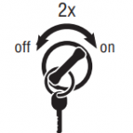
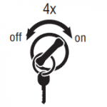
- To Retrieve Inactive Codes: Turn key on. Turn the key off and on 4 times within five seconds ending with the key in the on position. After 5 seconds, the Service light begins flashing two-digit fault codes. If no faults are active, the service light will flash code 25 (no codes).
- Two digit fault codes will be displayed in the gear display. Some vehicle may be equipped with a service light.
- Observe the sequence of flashes on the service light and record the codes. A 1- to 2-second pause separates each stored code, and the sequence automatically repeats after all codes have been flashed.

Clearing Fault Codes Manually
The following procedure clears all Inactive fault codes from the TECU’s memory. Active fault codes are automatically cleared when the fault has been corrected.
Note: You may use a PC-based service tool, such as ServiceRanger, to clear fault codes.
1. Place shift lever in neutral.
2. Set parking brake.
3. Turn key on with engine off.
4. Turn key off and on 6 times within 5 seconds ending with key on. Note: If the codes have been successfully cleared, the Service light will come on and stay on for five seconds. The gear display will show 25 (no codes).
5. Turn the key off and allow the system to power
down.
Fault Code Retrieval and Clearing in ServiceRanger
To view fault codes or to clear them, follow the procedures below.
View Active and Inactive Faults
1. Connect ServiceRanger to the 9-Way Diagnostic Connector.
2. Go to the “Tools” menu and select the “Communication” tab.
3. Select the appropriate communication device for J1587 and J1939.
4. Select “Connect” on the main page.
5. Select the “View Fault Codes” tab.
Note: Initial use requires all steps; however subsequent uses require only Step 4 and Step 5.
Clear Inactive Faults
1. Connect ServiceRanger to the 9-Way Diagnostic Connector.
2. Go to the “Tools” menu and select the “Communication” tab.
3. Select the appropriate communication device for J1587 and J1939.
4. Select “Connect” on the main page.
5. Select the “View Fault Codes” tab.
6. Select the “Clear Faults” button.
Note: Initial use requires all steps, however, subsequent uses require only Step 4 and Step 5.
Product Diagnostic Mode (PDM)
Product Diagnostic Mode (PDM)
Product Diagnostic Mode (PDM) is used to help diagnose Inactive codes that may have been set during normal driving. This diagnostic mode increases the sensitivity of the fault sensing capabilities.
This procedure tests loose, degraded and intermittent connections. See “ault Code Isolation Procedure Index below. Use the Index as a guide to the wiring and connectors that are associated with the Inactive fault codes. Flex the wiring harness and connectors and attempt to recreate the fault after activating PDM.
PDM is only to be used by a trained service technician in an authorized dealer.
To enter PDM mode:
Note: The vehicle will not start in Product Diagnostic Mode.
(PDM). Turn vehicle key “OFF” and allow the system to power down to exit PDM.
-
-
-
- Vehicle must be stationary, engine must not be running, vehicle parking brake must be set.
- Connect ServiceRanger to the 9-Way Diagnostic Connector.
- Select the “View Fault Codes” screen.
- Perform two key clicks of the ignition switch starting with the key on, and ending with the key on.
Note: An “88” may show up in the dash at key on, which is a normal power-up test of the display. - The gear display will flash a solid “PD” (Product Diagnostic Mode) and the mode will be activated.
- Flex the wiring harness and connectors and attempt to recreate the fault. If a fault becomes Active during PDM, ServiceRanger will display the fault with a status of Active.
- If a fault becomes Active during PDM, ServiceRanger will display the fault with a status of Active.
- If a fault is detected, exit PDM mode and perform the corresponding fault code troubleshooting procedure. See Fault Code Isolation Procedure Index below.
Note: Active codes set during PDM mode will not be stored as inactive. - To exit PDM mode, power the system down by turning the key off.
-
-
PDM will only work with the following Inactive codes
9, 10, 14, 16, 17, 18, 19, 22, 24, 32, 33, 34, 35, 36, 38, 39, 40, 48, 49, 50, 51, 52, 56, 58, 59, 60, 61, 63, 76, 87, 88, 89, 95, 118
The FMI (Failure Mode Identifier)
The FMI (Failure Mode Identifier) is used along with the SPN to provide specific information that relates to a diagnostic trouble code (DTC). The FMI may indicate that a problem with an electronic circuit or an electronic component has been detected. The FMI may also indicate that an abnormal operating condition has been detected.
FMI – Description
| 0 | High – most severe |
| 1 | Low – most severe |
| 2 | Erratic, Intermittent, or Incorrect |
| 3 | Voltage Above Normal |
| 4 | Voltage Below Normal |
| 5 | Current Below Normal |
| 6 | Current Above Normal |
| 7 | Not Responding Properly |
| 8 | Abnormal Frequency, Pulse Width, or Period |
| 9 | Abnormal Update Rate |
| 10 | Abnormal Rate of Change |
| 11 | Other Failure Mode |
| 12 | Failure |
| 13 | Out of Calibration |
| 14 | Special Instruction |
| 15 | High – least severe |
| 16 | High – moderate severity |
| 17 | Low – least severe |
| 18 | Low – moderate severity |
| 19 | Data Error |
| 20 | Data Drifted High |
| 21 | Data Drifted Low |
| 31 | – |

Any transmission part you need we have it! Same day shipping available, worldwide.
NEED FREE SUPPORT FROM ONE OF OUR EXPERTS?