[fusion_builder_container hundred_percent=”no” hundred_percent_height=”no” hundred_percent_height_scroll=”no” hundred_percent_height_center_content=”yes” equal_height_columns=”no” menu_anchor=”” hide_on_mobile=”small-visibility,medium-visibility,large-visibility” status=”published” publish_date=”” class=”” id=”” background_color=”” background_image=”” background_position=”center center” background_repeat=”no-repeat” fade=”no” background_parallax=”none” enable_mobile=”no” parallax_speed=”0.3″ video_mp4=”” video_webm=”” video_ogv=”” video_url=”” video_aspect_ratio=”16:9″ video_loop=”yes” video_mute=”yes” video_preview_image=”” border_size=”” border_color=”” border_style=”solid” margin_top=”35″ margin_bottom=”” padding_top=”” padding_right=”” padding_bottom=”” padding_left=””][fusion_builder_row][fusion_builder_column type=”1_1″ layout=”1_1″ spacing=”” center_content=”no” link=”” target=”_self” min_height=”” hide_on_mobile=”small-visibility,medium-visibility,large-visibility” class=”” id=”” background_color=”” background_image=”” background_image_id=”” background_position=”left top” background_repeat=”no-repeat” hover_type=”none” border_size=”0″ border_color=”” border_style=”solid” border_position=”all” padding_top=”” padding_right=”” padding_bottom=”” padding_left=”” margin_top=”” margin_bottom=”” animation_type=”” animation_direction=”left” animation_speed=”0.3″ animation_offset=”” last=”no”][fusion_text columns=”” column_min_width=”” column_spacing=”” rule_style=”default” rule_size=”” rule_color=”” hide_on_mobile=”small-visibility,medium-visibility,large-visibility” class=”” id=””]
Eaton Fuller Hybrid Transmission Fault Code 116 – High Voltage Relays -(MY08 Wunnengen)
[/fusion_text][/fusion_builder_column][/fusion_builder_row][/fusion_builder_container][fusion_builder_container hundred_percent=”no” hundred_percent_height=”no” hundred_percent_height_scroll=”no” hundred_percent_height_center_content=”yes” equal_height_columns=”no” menu_anchor=”” hide_on_mobile=”small-visibility,medium-visibility,large-visibility” status=”published” publish_date=”” class=”” id=”” background_color=”” background_image=”” background_position=”center center” background_repeat=”no-repeat” fade=”no” background_parallax=”none” enable_mobile=”no” parallax_speed=”0.3″ video_mp4=”” video_webm=”” video_ogv=”” video_url=”” video_aspect_ratio=”16:9″ video_loop=”yes” video_mute=”yes” video_preview_image=”” border_size=”” border_color=”” border_style=”solid” margin_top=”” margin_bottom=”” padding_top=”” padding_right=”” padding_bottom=”” padding_left=””][fusion_builder_row][fusion_builder_column type=”1_1″ layout=”1_1″ spacing=”” center_content=”no” link=”” target=”_self” min_height=”” hide_on_mobile=”small-visibility,medium-visibility,large-visibility” class=”” id=”” background_color=”” background_image=”” background_image_id=”” background_position=”left top” background_repeat=”no-repeat” hover_type=”none” border_size=”0″ border_color=”” border_style=”solid” border_position=”all” padding_top=”” padding_right=”” padding_bottom=”” padding_left=”” margin_top=”” margin_bottom=”” animation_type=”” animation_direction=”left” animation_speed=”0.3″ animation_offset=”” last=”no”][fusion_text columns=”” column_min_width=”” column_spacing=”” rule_style=”default” rule_size=”” rule_color=”” hide_on_mobile=”small-visibility,medium-visibility,large-visibility” class=”” id=””]
Schold Code fir Eaton Hybrid Fuert Wunnengen Modeller (MY08) EH-8E306A-U, EH-8E306A-UPG, EH-8E306A-EROP, EH-8E306A-CD, EH-8E306A-T, EH-6E606B-CD. Liest hei ënnendrënner fir ze léieren wéi een testen, kloer an Schold Code Feeler fir Är Freightliner befestegt, Mack, Peterbilt, Kenworth, Volvo, international, an Schwéierindustrie-Pflicht Camion an Equipementer. The High-Voltage Relays are located inside the Power Electronics Carrier (PEC) am impressionéiert Box Unitéit. There is 1 precharge relay on the positive side, an additional relay on the positive, an 1 on the negative for a total of 3. Dës weider sinn normalerweis oppen wann de System ugefaangen ass. Déi weider sinn duerch d'Inverter kontrolléiert.
Schold Code 116 – High Voltage Relays Detection
Déi folgend Obama mussen erfëllt ginn, ier de System d'Schold bieden:
- Inverter ignition Volt ass méi grouss wéi 7 volts a manner wéi 16 volts.
Note: Wann en d'Aarbechtslosegkeet Code troubleshooting kuckt an der Produit Diagnostic Régime (PDM)
Konditiounen ze setzen Fault Code aktive
- FMI 10 is set when the Inverter detects the input voltage measured at the capacitor is less than 210 volts within 3 seconds after the sub-relay closed in the Relay Box.
- FMI 14 is set when only the negative relay in the Relay Box is on and capacitor voltage decreases less than 10 volts/5 seconds when initial capacitor voltage was greater than 200 volts and motor speed less than 500 min-1, or there is a detect error in the initial check.
Standardsprooch Wann Fault Code 116 ass gesat déi folgend Konditioune geschéien:
- Amber "Check Hybrid" Liicht Phase fir FMI 10 and remains solid for FMI 14.
- Schold ass an HCM Erënnerung gespäichert.
- Inverter shuts héich-Volt System ugefaangen.
- HCM weider d'Hybrid Gefier an engem Diesel-nëmmen Modus ze kontrolléieren.
- Transmissioun Standardastellungen ufänken méngem ze 1..
[/fusion_text][fusion_text columns=”” column_min_width=”” column_spacing=”” rule_style=”default” rule_size=”” rule_color=”” hide_on_mobile=”small-visibility,medium-visibility,large-visibility” class=”” id=””]
Konditiounen ze setzen Fault Code d'Aarbechtslosegkeet
Nëmmen d'Aarbechtslosegkeet Feeler kann aus Signal Electronic Kontrolléiere Eenheetspräis geschëppt ginn (TECU) oder HCM Geschicht benotzt ServiceRanger. D'TECU kläert automatesch de Feeler vun der Geschicht 200 Stonnen an der HCM kläert automatesch de Feeler vu Geschicht no der Schold ass d'Aarbechtslosegkeet fir 200 Stonnen.
Dëse Feeler Code kann duerch all vun de folgenden verursaacht ginn:
- FMI 10
- PEC
- APG
- Inverter
- DC high-voltage cable
- DC cable interlock loops
- Obstruktioun lénksen
- Service lénksen
- FMI 14
- Inverter
- PEC
[/fusion_text][/fusion_builder_column][/fusion_builder_row][/fusion_builder_container][fusion_builder_container hundred_percent=”no” hundred_percent_height=”no” hundred_percent_height_scroll=”no” hundred_percent_height_center_content=”yes” equal_height_columns=”no” menu_anchor=”” hide_on_mobile=”small-visibility,medium-visibility,large-visibility” status=”published” publish_date=”” class=”” id=”” background_color=”” background_image=”” background_position=”center center” background_repeat=”no-repeat” fade=”no” background_parallax=”none” enable_mobile=”no” parallax_speed=”0.3″ video_mp4=”” video_webm=”” video_ogv=”” video_url=”” video_aspect_ratio=”16:9″ video_loop=”yes” video_mute=”yes” video_preview_image=”” border_size=”” border_color=”” border_style=”solid” margin_top=”” margin_bottom=”” padding_top=”” padding_right=”” padding_bottom=”” padding_left=””][fusion_builder_row][fusion_builder_column type=”1_1″ layout=”1_1″ spacing=”” center_content=”no” link=”” target=”_self” min_height=”” hide_on_mobile=”small-visibility,medium-visibility,large-visibility” class=”” id=”” background_color=”” background_image=”” background_image_id=”” background_position=”left top” background_repeat=”no-repeat” hover_type=”none” border_size=”0″ border_color=”” border_style=”solid” border_position=”all” padding_top=”” padding_right=”” padding_bottom=”” padding_left=”” margin_top=”” margin_bottom=”” animation_type=”” animation_direction=”left” animation_speed=”0.3″ animation_offset=”” last=”no”][fusion_text columns=”” column_min_width=”” column_spacing=”” rule_style=”default” rule_size=”” rule_color=”” hide_on_mobile=”small-visibility,medium-visibility,large-visibility” class=”” id=””]
Schold Code 116 – High Voltage Relays Test
[/fusion_text][/fusion_builder_column][/fusion_builder_row][/fusion_builder_container][fusion_builder_container hundred_percent=”no” hundred_percent_height=”no” hundred_percent_height_scroll=”no” hundred_percent_height_center_content=”yes” equal_height_columns=”no” menu_anchor=”” hide_on_mobile=”small-visibility,medium-visibility,large-visibility” status=”published” publish_date=”” class=”” id=”” background_color=”” background_image=”” background_position=”center center” background_repeat=”no-repeat” fade=”no” background_parallax=”none” enable_mobile=”no” parallax_speed=”0.3″ video_mp4=”” video_webm=”” video_ogv=”” video_url=”” video_aspect_ratio=”16:9″ video_loop=”yes” video_mute=”yes” video_preview_image=”” border_size=”” border_color=”” border_style=”solid” margin_top=”” margin_bottom=”” padding_top=”” padding_right=”” padding_bottom=”” padding_left=””][fusion_builder_row][fusion_builder_column type=”1_1″ layout=”1_1″ spacing=”” center_content=”no” link=”” target=”_self” min_height=”” hide_on_mobile=”small-visibility,medium-visibility,large-visibility” class=”” id=”” background_color=”” background_image=”” background_image_id=”” background_position=”left top” background_repeat=”no-repeat” hover_type=”none” border_size=”0″ border_color=”” border_style=”solid” border_position=”all” padding_top=”” padding_right=”” padding_bottom=”” padding_left=”” margin_top=”” margin_bottom=”” animation_type=”” animation_direction=”left” animation_speed=”0.3″ animation_offset=”” last=”no”][fusion_text columns=”” column_min_width=”” column_spacing=”” rule_style=”default” rule_size=”” rule_color=”” hide_on_mobile=”small-visibility,medium-visibility,large-visibility” class=”” id=””]
Komponent Umeldung MY08 Wunnengen:
[/fusion_text][/fusion_builder_column][/fusion_builder_row][/fusion_builder_container][fusion_builder_container hundred_percent=”yes” hundred_percent_height=”no” hundred_percent_height_scroll=”no” hundred_percent_height_center_content=”yes” equal_height_columns=”no” menu_anchor=”” hide_on_mobile=”small-visibility,medium-visibility,large-visibility” status=”published” publish_date=”” class=”” id=”” background_color=”” background_image=”” background_position=”center center” background_repeat=”no-repeat” fade=”no” background_parallax=”none” enable_mobile=”no” parallax_speed=”0.3″ video_mp4=”” video_webm=”” video_ogv=”” video_url=”” video_aspect_ratio=”16:9″ video_loop=”yes” video_mute=”yes” video_preview_image=”” border_size=”” border_color=”” border_style=”solid” margin_top=”” margin_bottom=”” padding_top=”” padding_right=”10%” padding_bottom=”” padding_left=”10%”][fusion_builder_row][fusion_builder_column type=”1_3″ layout=”1_3″ spacing=”” center_content=”no” link=”” target=”_self” min_height=”” hide_on_mobile=”small-visibility,medium-visibility,large-visibility” class=”” id=”” background_color=”” background_image=”” background_image_id=”” background_position=”left top” background_repeat=”no-repeat” hover_type=”none” border_size=”0″ border_color=”” border_style=”solid” border_position=”all” padding_top=”” padding_right=”” padding_bottom=”” padding_left=”” margin_top=”” margin_bottom=”” animation_type=”” animation_direction=”left” animation_speed=”0.3″ animation_offset=”” last=”no”][fusion_imageframe image_id=”14474|full” max_width=”” style_type=”” blur=”” stylecolor=”” hover_type=”none” bordersize=”” bordercolor=”” borderradius=”” align=”center” lightbox=”no” gallery_id=”” lightbox_image=”” lightbox_image_id=”” alt=”Delphi 56-Way Mating wäert bewegen View” link=”” linktarget=”_self” hide_on_mobile=”small-visibility,medium-visibility,large-visibility” class=”” id=”” animation_type=”” animation_direction=”left” animation_speed=”0.3″ animation_offset=””]https://www.globaltransmissionsupply.com/wp-content/uploads/Inverter-56-Way-Mating-Connector-View.jpg[/fusion_imageframe][fusion_text columns=”” column_min_width=”” column_spacing=”” rule_style=”default” rule_size=”” rule_color=”” hide_on_mobile=”small-visibility,medium-visibility,large-visibility” class=”” id=””]
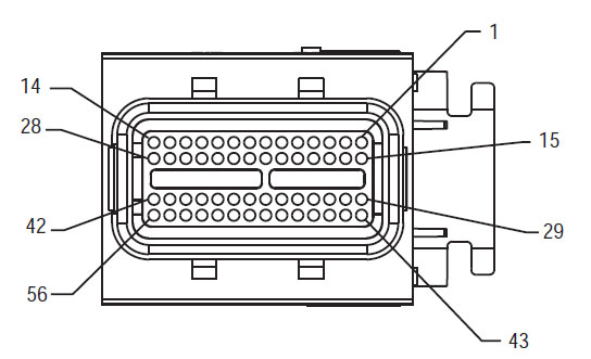
56-Manéier Mating wäert bewegen View
[/fusion_text][/fusion_builder_column][fusion_builder_column type=”1_3″ layout=”1_3″ spacing=”” center_content=”no” link=”” target=”_self” min_height=”” hide_on_mobile=”small-visibility,medium-visibility,large-visibility” class=”” id=”” background_color=”” background_image=”” background_image_id=”” background_position=”left top” background_repeat=”no-repeat” hover_type=”none” border_size=”0″ border_color=”” border_style=”solid” border_position=”all” padding_top=”” padding_right=”” padding_bottom=”” padding_left=”” margin_top=”” margin_bottom=”” animation_type=”” animation_direction=”left” animation_speed=”0.3″ animation_offset=”” last=”no”][fusion_imageframe image_id=”14635|full” max_width=”” style_type=”” blur=”” stylecolor=”” hover_type=”none” bordersize=”” bordercolor=”” borderradius=”” align=”center” lightbox=”no” gallery_id=”” lightbox_image=”” lightbox_image_id=”” alt=”Héich Volt DC wäert bewegen View Yazaki wäert bewegen” link=”” linktarget=”_self” hide_on_mobile=”small-visibility,medium-visibility,large-visibility” class=”” id=”” animation_type=”” animation_direction=”left” animation_speed=”0.3″ animation_offset=””]https://www.globaltransmissionsupply.com/wp-content/uploads/High-Voltage-DC-Connector-View.jpg[/fusion_imageframe][fusion_text columns=”” column_min_width=”” column_spacing=”” rule_style=”default” rule_size=”” rule_color=”” hide_on_mobile=”small-visibility,medium-visibility,large-visibility” class=”” id=””]
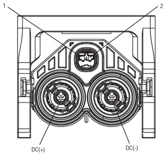
Héich Volt DC wäert bewegen View Yazaki wäert bewegen
[/fusion_text][/fusion_builder_column][fusion_builder_column type=”1_3″ layout=”1_3″ spacing=”” center_content=”no” link=”” target=”_self” min_height=”” hide_on_mobile=”small-visibility,medium-visibility,large-visibility” class=”” id=”” background_color=”” background_image=”” background_image_id=”” background_position=”left top” background_repeat=”no-repeat” hover_type=”none” border_size=”0″ border_color=”” border_style=”solid” border_position=”all” padding_top=”” padding_right=”” padding_bottom=”” padding_left=”” margin_top=”” margin_bottom=”” animation_type=”” animation_direction=”left” animation_speed=”0.3″ animation_offset=”” last=”no”][fusion_imageframe image_id=”14213|medium” max_width=”” style_type=”” blur=”” stylecolor=”” hover_type=”none” bordersize=”” bordercolor=”” borderradius=”” align=”center” lightbox=”no” gallery_id=”” lightbox_image=”” lightbox_image_id=”” alt=”Mating Connector View Deutsch 19 – Manéier” link=”” linktarget=”_self” hide_on_mobile=”small-visibility,medium-visibility,large-visibility” class=”” id=”” animation_type=”” animation_direction=”left” animation_speed=”0.3″ animation_offset=””]https://www.globaltransmissionsupply.com/wp-content/uploads/Eaton-Fuller-Harness-Connector-View-300×289.jpg[/fusion_imageframe][fusion_text columns=”” column_min_width=”” column_spacing=”” rule_style=”default” rule_size=”” rule_color=”” hide_on_mobile=”small-visibility,medium-visibility,large-visibility” class=”” id=””]
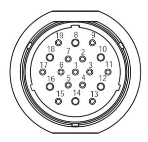
Mating Connector View Deutsch 19 – Manéier
[/fusion_text][/fusion_builder_column][/fusion_builder_row][/fusion_builder_container][fusion_builder_container hundred_percent=”no” hundred_percent_height=”no” hundred_percent_height_scroll=”no” hundred_percent_height_center_content=”yes” equal_height_columns=”no” menu_anchor=”” hide_on_mobile=”small-visibility,medium-visibility,large-visibility” status=”published” publish_date=”” class=”” id=”” background_color=”” background_image=”” background_position=”center center” background_repeat=”no-repeat” fade=”no” background_parallax=”none” enable_mobile=”no” parallax_speed=”0.3″ video_mp4=”” video_webm=”” video_ogv=”” video_url=”” video_aspect_ratio=”16:9″ video_loop=”yes” video_mute=”yes” video_preview_image=”” border_size=”” border_color=”” border_style=”solid” margin_top=”” margin_bottom=”” padding_top=”” padding_right=”” padding_bottom=”” padding_left=””][fusion_builder_row][fusion_builder_column type=”1_1″ layout=”1_1″ spacing=”” center_content=”no” link=”” target=”_self” min_height=”” hide_on_mobile=”small-visibility,medium-visibility,large-visibility” class=”” id=”” background_image_id=”” background_color=”#000000″ background_image=”” background_position=”left top” undefined=”” background_repeat=”no-repeat” hover_type=”none” border_size=”0″ border_color=”” border_style=”solid” border_position=”all” padding_top=”” padding_right=”” padding_bottom=”” padding_left=”” margin_top=”” margin_bottom=”” animation_type=”” animation_direction=”left” animation_speed=”0.3″ animation_offset=”” last=”no”][fusion_text columns=”” column_min_width=”” column_spacing=”” rule_style=”default” rule_size=”” rule_color=”” hide_on_mobile=”small-visibility,medium-visibility,large-visibility” class=”” id=””]
NOTÉIERT: Kuckt an der Eaton Hybrid Komponent a wäert bewegen Location fir wäert bewegen Locations an MY08 Wunnengen
[/fusion_text][/fusion_builder_column][fusion_builder_column type=”1_1″ layout=”1_1″ spacing=”” center_content=”no” link=”” target=”_self” min_height=”” hide_on_mobile=”small-visibility,medium-visibility,large-visibility” class=”” id=”” background_color=”” background_image=”” background_image_id=”” background_position=”left top” background_repeat=”no-repeat” hover_type=”none” border_size=”0″ border_color=”” border_style=”solid” border_position=”all” padding_top=”” padding_right=”” padding_bottom=”” padding_left=”” margin_top=”” margin_bottom=”” animation_type=”” animation_direction=”left” animation_speed=”0.3″ animation_offset=”” last=”no”][fusion_imageframe image_id=”14666|full” max_width=”” style_type=”” blur=”” stylecolor=”” hover_type=”none” bordersize=”” bordercolor=”” borderradius=”” align=”center” lightbox=”no” gallery_id=”” lightbox_image=”” lightbox_image_id=”” alt=”Inverter PEC connectors Eaton Fuller Hybrid transmission” link=”” linktarget=”_self” hide_on_mobile=”small-visibility,medium-visibility,large-visibility” class=”” id=”” animation_type=”” animation_direction=”left” animation_speed=”0.3″ animation_offset=””]https://www.globaltransmissionsupply.com/wp-content/uploads/Inverter-PEC-connectors.png[/fusion_imageframe][/fusion_builder_column][/fusion_builder_row][/fusion_builder_container][fusion_builder_container hundred_percent=”no” hundred_percent_height=”no” hundred_percent_height_scroll=”no” hundred_percent_height_center_content=”yes” equal_height_columns=”no” menu_anchor=”” hide_on_mobile=”small-visibility,medium-visibility,large-visibility” status=”published” publish_date=”” class=”” id=”” background_color=”” background_image=”” background_position=”center center” background_repeat=”no-repeat” fade=”no” background_parallax=”none” enable_mobile=”no” parallax_speed=”0.3″ video_mp4=”” video_webm=”” video_ogv=”” video_url=”” video_aspect_ratio=”16:9″ video_loop=”yes” video_mute=”yes” video_preview_image=”” border_size=”” border_color=”” border_style=”solid” margin_top=”” margin_bottom=”” padding_top=”” padding_right=”” padding_bottom=”” padding_left=””][fusion_builder_row][fusion_builder_column type=”1_1″ layout=”1_1″ spacing=”” center_content=”no” link=”” target=”_self” min_height=”” hide_on_mobile=”small-visibility,medium-visibility,large-visibility” class=”” id=”” background_color=”” background_image=”” background_image_id=”” background_position=”left top” background_repeat=”no-repeat” hover_type=”none” border_size=”0″ border_color=”” border_style=”solid” border_position=”all” padding_top=”” padding_right=”” padding_bottom=”” padding_left=”” margin_top=”” margin_bottom=”” animation_type=”” animation_direction=”left” animation_speed=”0.3″ animation_offset=”” last=”no”][fusion_modal name=”warnings_cautions” title=”Warnungen & Cautions” size=”large” background=”” border_color=”” show_footer=”yes” class=”” id=””]Gefor: Gefor weist datt Dir schwéier verletzt oder ëmbruecht sidd wann net déi uginn Prozedur befollegt.
Opgepasst: Opgepasst beweist en direkten iwwerschloen, wat zu schwéiere perséinleche Verletzunge féiere kéint wann Dir déi uginn Prozedur net befollegt.
eruwoen: Opgepasst weist datt Gefier- oder Eegeschied kéint optrieden wann Dir déi uginn Prozedur net befollegt.
Note: Notiz weist zousätzlech Detailer un, déi bei der Diagnos oder der Reparatur vun engem Komponent / System hëllefe wäerten.
Follegt der spezifizéierter Prozeduren am uginn fir Persouneschued ze vermeiden:
1. Wann d'Héich-Volt bësse verluer sinn ronderëm den Auto an der aschreiwen op der PEC installéiert ass, déi eenzeg Persoun, déi d'Gefier bis Ufank ginn erlaabt soll ass déi Persoun déi de aschreiwen Tag ënnerschriwwen.
2. Virun schaffen op engem Gefier oder loosst der Cab iwwerdeems de Motor ass Lafen, Dir sollt der Verréckelung Hiewel am "N" Plaz vum Parking Brems- Formatioun, a blockéieren d'Rieder.
3. Fir Sécherheet Grënn, ëmmer engagéieren de Service Bremsen virun méngem Positiounen vum "N." zu auswielen
4. Éier ab engem Gefier ëmmer an de Chauffeur d'Sëtz Riichterstull ginn, wielt "N" op der Verréckelung Kontroll, a setzen de Parking Bremsen.
5. An Gefierer mat ePTO, de Motor an / oder
Motor / Generator kann an ePTO Régime ufänken. Ni all Ënnerhalt Leeschtunge oder op Gefier Aarbecht, iwwerdeems an dësem Modus.
6. 12-Volt Des positiv (+) an negativ (-) muss virun all Schweess op all Hybrid equipéiert Gefier disconnected ginn.
eruwoen: Follegt der spezifizéierter Prozeduren am uginn fir Equipement Feelfunktioun oder Schued ze verhënneren.
eruwoen: Loosst d'Parkbrems net entloossen oder probéiert e Gang auszewielen bis de Loftdrock um richtegen Niveau ass.
eruwoen: Fir e Schued un der Iwwerdroung beim Ofschleefen ze vermeiden, plazéiert de Schalthiewel an "N" an hëlt d'Fuerwieder vum Buedem oder trennt d'Dreiwelinn aus.
High-Volt Warnunge & Cautions
- Benotzen CO2 oder Mangue Chemeschen Feierläscher.
- Déi héich-Volt wiring ass an orange Isolatioun oder gestierzt tubing a markéiert mat Warnung Etiketten um kommentéieren Daach.
- All Eaton® Hybrid Diesel / elektresch Autoen markéiert ginn "Hybrid’ op der ausserhalb vun der Gefier, zesumme mat der Verréckelung Label op der Bindestrich.
- Akeef ze Equipment fir spezifesch Plaz vun Chassis schéi Hybrid Komponente.
- NET an der orange héich-Volt Kabelen Géigewier.
- Wëllt Géigewier NET an oder op der PEC.
- Wëllt Géigewier NET an oder op der DC / DC Hunnefest.
- Wëllt Géigewier NET an oder de Inverter oppen.
A Prellbock Zone muss an héich-Volt isoléiert Gummistécker Händschen virbereet ginn (Klass 0 mat Lieder protectors) virun ze schaffen op héich-Volt sinn néideg. Echec dës Instruktiounen ze verfollegen kann an schwéieren Persouneschued oder Doud Resultat.
D'Gummistécker-isoléiert Händschen, datt während schaffen op der Héich-Volt System sinn Klass drënner muss 0 mat Lieder protectors. D'Gummistécker Händschen sollen am "Diagnostic Tools / Service Publikatiounen" op Säit fonnt folgende der Gummistécker Isolatioun Händschen lafend Prozedur virun all Gebrauch getest ginn 6. Echec dës Instruktiounen ze verfollegen kann an schwéieren Persouneschued oder Doud Resultat.
Virun doran oder schaffen op all héich-Volt Kabelen oder Komponente der "High-Volt Service Wann an Power-Up AGRËFF" op Säit 4 soll duerno. Echec dës Instruktiounen ze verfollegen kann an schwéieren Persouneschued oder Doud Resultat.
D'aschreiwen an Tagout Apparater soll nëmmen vun den Techniker geläscht ginn, datt d'aschreiwen an Tagout Apparaten op der Gefier gesat. Echec dës Instruktiounen ze verfollegen kann an schwéieren Persouneschued oder Doud Resultat.
High-Volt Gummistécker isoléiert Händschen (Klass 0 mat Lieder protectors) muss hunn drënner ginn wann op all schaffen
héich-Volt Kabelen. De "High-Volt Service Wann an Power-Up AGRËFF" op Säit 4 muss virun Stoppen all héich-Volt Kabelen gefollegt ginn. Echec dës Instruktiounen ze verfollegen kann an schwéieren Persouneschued oder Doud Resultat.
High-Volt Kabelen an wiring sinn orange an enthält eng Warnung Label um kommentéieren. High-Volt Komponente sinn mat engem Label markéiert. High-Volt Gummistécker isoléiert Händschen (Klass 0 mat Lieder protectors) muss benotzt ginn, wann op all vun dësen Komponente schaffen. Echec dës Instruktiounen ze verfollegen kann an schwéieren Persouneschued oder Doud Resultat.
High-Volt Service Wann Démarchen

1. Follegt "High-Volt Work Area" Prozedur.
2. Situéiert de roude PEC Service lénksen op der erfollegräich PEC a weist schalt ugefaangen.
3. Ewechzehuelen de Service lénksen Deckt an installéiert der aschreiwen erhéijen (J48506).
4. Ratifizéiert Tag dem aschreiwen erhéijen.
5. Garantéieren de PEC Service lénksen kann net aus der ugefaangen Positioun réckelen.
6. Erlaben de System fir e Minimum un Formatioun vun 5 Minutten héich Volt zu Offlossquantitéit.
7. Connect ServiceRanger an der Data Monitor Colombera Vue 116 "High-Volt Des Potential huet." Genannt Benotzt SPN 520323 "Des Volt RB" fir J1939 Verbindung (impressionéiert Box).
8. D'Volt soll 30 volts oder manner. Wann der Volt ass virun 30 volts, do schaffen net op den Auto a Kontakt Eaton® um 1-800-826-HELP (4357).
9. Tour ignition Schlëssel ugefaangen a viru ze flécken oder troubleshooting Schrëtt.
Note: D'Volt Drëpsen ze null wann de Schlëssel ugefaangen ass.
High-Volt Service Power-Up Prozedur
1. Installéiert all héich-Volt kommentéieren an hir gespaart Positiounen.
2. Wann Dir déi Persoun schaffen op der Gefier sinn, ewechzehuelen der aschreiwen erhéijen an Tag.
3. Installéieren der aschreiwen erhéijen iwwer de Service lénksen.
4. Pull de Service lénksen aus a loosse Gefier Formatioun fir 2 Minutten.
5. Start vehicle when appropriate.[/fusion_modal][fusion_modal name=”component_location” title=”Eaton Hybrid Komponent a wäert bewegen Location ” size=”large” background=”#ffffff” border_color=”” show_footer=”yes” class=”” id=””]

[/fusion_modal][fusion_modal name=”component_location2″ title=”Eaton Hybrid Komponent a wäert bewegen Location MY09 Wunnengen” size=”large” background=”#ffffff” border_color=”” show_footer=”yes” class=”” id=””]

[/fusion_modal][/fusion_builder_column][/fusion_builder_row][/fusion_builder_container][fusion_builder_container hundred_percent=”no” hundred_percent_height=”no” hundred_percent_height_scroll=”no” hundred_percent_height_center_content=”yes” equal_height_columns=”no” menu_anchor=”” hide_on_mobile=”small-visibility,medium-visibility,large-visibility” status=”published” publish_date=”” class=”” id=”” background_color=”” background_image=”” background_position=”center center” background_repeat=”no-repeat” fade=”no” background_parallax=”none” enable_mobile=”no” parallax_speed=”0.3″ video_mp4=”” video_webm=”” video_ogv=”” video_url=”” video_aspect_ratio=”16:9″ video_loop=”yes” video_mute=”yes” video_preview_image=”” border_size=”” border_color=”” border_style=”solid” margin_top=”” margin_bottom=”” padding_top=”” padding_right=”” padding_bottom=”” padding_left=””][fusion_builder_row][fusion_builder_column type=”1_1″ layout=”1_1″ spacing=”” center_content=”no” link=”” target=”_self” min_height=”” hide_on_mobile=”small-visibility,medium-visibility,large-visibility” class=”” id=”” background_color=”” background_image=”” background_image_id=”” background_position=”left top” background_repeat=”no-repeat” hover_type=”none” border_size=”0″ border_color=”” border_style=”solid” border_position=”all” padding_top=”” padding_right=”” padding_bottom=”” padding_left=”” margin_top=”” margin_bottom=”” animation_type=”” animation_direction=”left” animation_speed=”0.3″ animation_offset=”” last=”no”][fusion_content_boxes layout=”clean-horizontal” columns=”2″ title_size=”18px” heading_size=”3″ title_color=”#ffffff” body_color=”#ffffff” backgroundcolor=”#4f4f4f” icon=”” iconflip=”” iconrotate=”” iconspin=”no” iconcolor=”” icon_circle=”” icon_circle_radius=”” circlecolor=”” circlebordersize=”” circlebordercolor=”” outercirclebordersize=”” outercirclebordercolor=”” icon_size=”” icon_hover_type=”” hover_accent_color=”” image=”” image_id=”” image_width=”” image_height=”” link_type=”” button_span=”” link_area=”” link_target=”” icon_align=”left” animation_type=”” animation_delay=”” animation_offset=”” animation_direction=”left” animation_speed=”0.3″ margin_top=”” margin_bottom=”” hide_on_mobile=”small-visibility,medium-visibility,large-visibility” class=”” id=””][fusion_content_box title=”SCHRËTT 1. Z'iwwerpréiwen FMIs presentéieren.” backgroundcolor=”” icon=”” iconflip=”” iconrotate=”” iconspin=”no” iconcolor=”” circlecolor=”” circlebordersize=”” circlebordercolor=”” outercirclebordersize=”” outercirclebordercolor=”” image=”” image_id=”” image_width=”” image_height=”” link=”” linktext=”viruliesen” link_target=”” animation_type=”” animation_direction=”left” animation_speed=”0.3″ animation_offset=””]
- Iwwerschaffen an no der Warnungen & Cautions.
- Recuperéieren aktive Schold Coden an FMIs mat ServiceRanger der 9-Way Diagnostic wäert bewegen mat.
Gefor: gesinn High-Voltage Service Shutdown a Power-Up Prozeduren. Follegt de Prozeduren Schock ze vermeiden, verbrennt oder Doud vum improperly déviéiert héich-Volt. - Wat FMIs präsent sinn
- Wann Fault Code 116 FMI 14 ass opgezielt, WEIDER Step 9.
- Wann Fault Code 116 FMI 10 ass opgezielt, WEIDER Step 2.
- If no Fault Codes are listed, The Service Switch was pushed in. WEIDER Step 10.
[/fusion_content_box][fusion_content_box title=”SCHRËTT 2. Verify Data Monitor parameters.” backgroundcolor=”” icon=”” iconflip=”” iconrotate=”” iconspin=”no” iconcolor=”” circlecolor=”” circlebordersize=”” circlebordercolor=”” outercirclebordersize=”” outercirclebordercolor=”” image=”” image_id=”” image_width=”” image_height=”” link=”” linktext=”viruliesen” link_target=”” animation_type=”” animation_direction=”left” animation_speed=”0.3″ animation_offset=””]
- Schlëssel op.
- Connect ServiceRanger zu der 9.-Way Diagnostic wäert bewegen am Cab.
- Wielt de "Data Monitor" Optioun.
- View the Battery Pack Voltage (BCU1) Colombera 118 in the high- voltage Battery list:
- If the Battery Pack Voltage (BCU1) Colombera 118 is greater than 200 volts, WEIDER Step 3.
- If the Battery Pack Voltage (BCU1) Colombera 118 ass manner wéi 200 volts, schounen der Power Electronics Cambridge (PEC), duerno bei Step 10.
[/fusion_content_box][/fusion_content_boxes][fusion_content_boxes layout=”clean-horizontal” columns=”2″ title_size=”18px” heading_size=”3″ title_color=”#ffffff” body_color=”#ffffff” backgroundcolor=”#4f4f4f” icon=”” iconflip=”” iconrotate=”” iconspin=”no” iconcolor=”” icon_circle=”” icon_circle_radius=”” circlecolor=”” circlebordersize=”” circlebordercolor=”” outercirclebordersize=”” outercirclebordercolor=”” icon_size=”” icon_hover_type=”” hover_accent_color=”” image=”” image_id=”” image_width=”” image_height=”” link_type=”” button_span=”” link_area=”” link_target=”” icon_align=”left” animation_type=”” animation_delay=”” animation_offset=”” animation_direction=”left” animation_speed=”0.3″ margin_top=”” margin_bottom=”” hide_on_mobile=”small-visibility,medium-visibility,large-visibility” class=”” id=””][fusion_content_box title=”SCHRËTT 3. Verify continuity of Inverter connector circuits.” backgroundcolor=”” icon=”” iconflip=”” iconrotate=”” iconspin=”no” iconcolor=”” circlecolor=”” circlebordersize=”” circlebordercolor=”” outercirclebordersize=”” outercirclebordercolor=”” image=”” image_id=”” image_width=”” image_height=”” link=”” linktext=”viruliesen” link_target=”” animation_type=”” animation_direction=”left” animation_speed=”0.3″ animation_offset=””]
- Schlëssel ugefaangen.
- If the vehicle is not equipped with a DC/DC Converter or APG, skip this step.
- Using ASTM Class 0 electrical insulating rubber gloves with leather protectors, disconnect the DC cable for the DC/DC Converter and APG at the PEC.
- With the key off, temporarily remove the Lockout Bracket and pull the Service Switch out.
- Schlëssel op.
- Ass Fault Code 116 FMI 10 still Active in ServiceRanger?
- Wann Fault Code 116 FMI 10 is Active with the DC/DC Converter and APG disconnected, WEIDER Step 4.
- Wann Fault Code 116 FMI 10 is no longer Active with the DC/DC Converter and APG disconnected, key off and reinstall the Lockout Bracket on the PEC. Replace the Power Electronics Carrier (PEC), duerno bei Step 10.
[/fusion_content_box][fusion_content_box title=”SCHRËTT 4. Verify continuity of PEC connector circuits to ground.” backgroundcolor=”” icon=”” iconflip=”” iconrotate=”” iconspin=”” iconcolor=”” circlecolor=”” circlebordersize=”” circlebordercolor=”” outercirclebordersize=”” outercirclebordercolor=”” image=”” image_id=”” image_width=”” image_height=”” link=”” linktext=”” link_target=”” animation_type=”” animation_direction=”left” animation_speed=”0.3″ animation_offset=””]
- Schlëssel ugefaangen.
- Trennt der PEC 19-Way wäert bewegen.
- Temporarily remove the Lockout Bracket and pull the Service Switch out.
Note: Ensure the Key Switch is off. - Measure resistance at the PEC 19-Way Connector Terminal at the following pins:
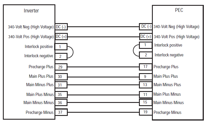
- Pin 17 zu Pin 19
- Pin 9 zu Pin 11
- Pin 13 zu Pin 15
- If the resistance between Pins 17 a Pin 19 ass 112-122 ohms an der Resistenz vum Pin 9 zu Pin 11 a Pin 13 zu Pin 15 sinn all 33-37 ohms, WEIDER Step 5.
- Wann Resistenz ass Gamme aus, WEIDER Step 6.
[/fusion_content_box][/fusion_content_boxes][fusion_content_boxes layout=”clean-horizontal” columns=”2″ title_size=”18px” heading_size=”3″ title_color=”#ffffff” body_color=”#ffffff” backgroundcolor=”#4f4f4f” icon=”” iconflip=”” iconrotate=”” iconspin=”no” iconcolor=”” icon_circle=”” icon_circle_radius=”” circlecolor=”” circlebordersize=”” circlebordercolor=”” outercirclebordersize=”” outercirclebordercolor=”” icon_size=”” icon_hover_type=”” hover_accent_color=”” image=”” image_id=”” image_width=”” image_height=”” link_type=”” button_span=”” link_area=”” link_target=”” icon_align=”left” animation_type=”” animation_delay=”” animation_offset=”” animation_direction=”left” animation_speed=”0.3″ margin_top=”” margin_bottom=”” hide_on_mobile=”small-visibility,medium-visibility,large-visibility” class=”” id=””][fusion_content_box title=”SCHRËTT 5. Verify continuity of Inverter connector circuits to ground.” backgroundcolor=”” icon=”” iconflip=”” iconrotate=”” iconspin=”no” iconcolor=”” circlecolor=”” circlebordersize=”” circlebordercolor=”” outercirclebordersize=”” outercirclebordercolor=”” image=”” image_id=”” image_width=”” image_height=”” link=”” linktext=”viruliesen” link_target=”” animation_type=”” animation_direction=”left” animation_speed=”0.3″ animation_offset=””]
- Schlëssel ugefaangen.
- Reconnect the PEC 19-Way Connector.
- Trennt der Inverter 56-Way wäert bewegen.
- Inspect the connector pins for damaged, corroded and/or loose wires.
- Measure resistance between the Inverter 56-Way Connector at the following pins:
- Pin 29 zu Pin 37
- Pin 30 zu Pin 35
- Pin 31 zu Pin 36 Note: der Inverter 56-Way wäert bewegen Police bei der bewegen verbannen FlexLanguage während der Resistenz Wäerter iwwerwaacht.
- Wann der Resistenz tëscht Pin 29 a Pin 37 ass 112-122 ohms an der Resistenz vum Pin 30 zu Pin 35 a Pin 31 zu Pin 36 sinn all 33-37 ohms, push the Service Switch on the PEC and reinstall the Lockout Bracket. WEIDER Step 8.
- Wann Resistenz ass Gamme aus, repair the Hybrid Harness between the PEC and Inverter, duerno bei Step 10.
[/fusion_content_box][fusion_content_box title=”SCHRËTT 6. Verify continuity of PEC connector circuits.” backgroundcolor=”” icon=”” iconflip=”” iconrotate=”” iconspin=”” iconcolor=”” circlecolor=”” circlebordersize=”” circlebordercolor=”” outercirclebordersize=”” outercirclebordercolor=”” image=”” image_id=”” image_width=”” image_height=”” link=”” linktext=”” link_target=”” animation_type=”” animation_direction=”left” animation_speed=”0.3″ animation_offset=””]
- Schlëssel ugefaangen.
- Remove the Air Filter Cover and Air Filter from the PEC. Refer to TRSM1000 for procedures.*
- An Inertia Switch is located at the front of the PEC inside the box and viewable when the Air Filter is removed.
- Using ASTM Class 0 electrical insulating rubber gloves with leather protectors, press the button on the top of the Inertia Switch until heard or felt a click. This switch must be depressed a set distance to reset the switch.
- Measure resistance at the PEC 19-Way Connector Terminal at the following pins:
- Pin 17 zu Pin 19
- Pin 9 zu Pin 11
- Pin 13 zu Pin 15
- qIf the resistance between Pin 17 a Pin 19 ass 112-122 ohms an der Resistenz vum Pin 9 zu Pin 11 a Pin 13 zu Pin 15 sinn all 33-37 ohms, the Inertia Switch was tripped. Test is complete. WEIDER Step 10.
- Wann Resistenz ass Gamme aus, push in the Service Switch on the PEC and reinstall the Lockout Bracket, duerno bei Step 7.
[/fusion_content_box][/fusion_content_boxes][fusion_content_boxes layout=”clean-horizontal” columns=”2″ title_size=”18px” heading_size=”3″ title_color=”#ffffff” body_color=”#ffffff” backgroundcolor=”#4f4f4f” icon=”” iconflip=”” iconrotate=”” iconspin=”no” iconcolor=”” icon_circle=”” icon_circle_radius=”” circlecolor=”” circlebordersize=”” circlebordercolor=”” outercirclebordersize=”” outercirclebordercolor=”” icon_size=”” icon_hover_type=”” hover_accent_color=”” image=”” image_id=”” image_width=”” image_height=”” link_type=”” button_span=”” link_area=”” link_target=”” icon_align=”left” animation_type=”” animation_delay=”” animation_offset=”” animation_direction=”left” animation_speed=”0.3″ margin_top=”” margin_bottom=”” hide_on_mobile=”small-visibility,medium-visibility,large-visibility” class=”” id=””][fusion_content_box title=”SCHRËTT 7. Verify continuity of Inverter connector circuits.” backgroundcolor=”” icon=”” iconflip=”” iconrotate=”” iconspin=”no” iconcolor=”” circlecolor=”” circlebordersize=”” circlebordercolor=”” outercirclebordersize=”” outercirclebordercolor=”” image=”” image_id=”” image_width=”” image_height=”” link=”” linktext=”viruliesen” link_target=”” animation_type=”” animation_direction=”left” animation_speed=”0.3″ animation_offset=””]
- Schlëssel ugefaangen.
- Disconnect the DC High-Voltage Cable at the PEC Bulkhead and at the Inverter Bulkhead.
- Measure resistance between the Low-Voltage Interlock Pins on the PEC side of the DC High-Voltage Cable:
Note: The Interlock Pins are the two small spade terminals located in the same opening.- If the resistance is 0–0.3 ohms between the Interlock Loop Pins, schounen der Power Electronics Cambridge (PEC), duerno bei Step 10.
- Wann Resistenz ass Gamme aus, der DC héich-Volt Kabel ze schounen, duerno bei Step 10.
[/fusion_content_box][fusion_content_box title=”SCHRËTT 8. Verify continuity of DC Cable from PEC to Inverter Connector circuits.” backgroundcolor=”” icon=”” iconflip=”” iconrotate=”” iconspin=”” iconcolor=”” circlecolor=”” circlebordersize=”” circlebordercolor=”” outercirclebordersize=”” outercirclebordercolor=”” image=”” image_id=”” image_width=”” image_height=”” link=”” linktext=”” link_target=”” animation_type=”” animation_direction=”left” animation_speed=”0.3″ animation_offset=””]
- Schlëssel ugefaangen.
- Disconnect the DC High-Voltage Cable at the PEC Bulkhead and the Inverter Bulkhead.
- Measure the resistance of each high-voltage circuit on the cable:
- If the resistance of each high-voltage circuit in the cable is 1 ohm oder manner, schounen der Inverter, duerno bei Step 10.
- Wann Resistenz ass Gamme aus, replace the DC High-Voltage Cable, duerno bei Step 10.
[/fusion_content_box][/fusion_content_boxes][fusion_content_boxes layout=”clean-horizontal” columns=”2″ title_size=”18px” heading_size=”3″ title_color=”#ffffff” body_color=”#ffffff” backgroundcolor=”#4f4f4f” icon=”” iconflip=”” iconrotate=”” iconspin=”no” iconcolor=”” icon_circle=”” icon_circle_radius=”” circlecolor=”” circlebordersize=”” circlebordercolor=”” outercirclebordersize=”” outercirclebordercolor=”” icon_size=”” icon_hover_type=”” hover_accent_color=”#f41000″ image=”” image_id=”” image_width=”” image_height=”” link_type=”” button_span=”” link_area=”” link_target=”” icon_align=”left” animation_type=”” animation_delay=”” animation_offset=”” animation_direction=”left” animation_speed=”0.3″ margin_top=”” margin_bottom=”” hide_on_mobile=”small-visibility,medium-visibility,large-visibility” class=”” id=””][fusion_content_box title=”SCHRËTT 9. Verify Data Monitor parameters.” backgroundcolor=”” icon=”” iconflip=”” iconrotate=”” iconspin=”” iconcolor=”” circlecolor=”” circlebordersize=”” circlebordercolor=”” outercirclebordersize=”” outercirclebordercolor=”” image=”” image_id=”” image_width=”” image_height=”” link=”” linktext=”” link_target=”” animation_type=”” animation_direction=”left” animation_speed=”0.3″ animation_offset=””]
- Connect ServiceRanger zu der 9.-Way Diagnostic wäert bewegen am Cab.
- Wielt de "Data Monitor" Optioun.
- View the following parameters in the High-Voltage Battery list.
- Battery Pack Voltage (BCU1) Colombera 118
- Battery Voltage PID 116
- If the voltage readings on PID 116 an Colombera 118 are within 10 volts vun all anere, schounen der Power Electronics Cambridge (PEC), duerno bei Step 10.
- If the voltage readings on PID 116 an Colombera 118 are greater than 10 volts vun all anere, schounen der Inverter, duerno bei Step 10.
[/fusion_content_box][fusion_content_box title=”SCHRËTT 10. z'iwwerpréiwen gefléckt.” backgroundcolor=”” icon=”” iconflip=”” iconrotate=”” iconspin=”no” iconcolor=”” circlecolor=”” circlebordersize=”” circlebordercolor=”” outercirclebordersize=”” outercirclebordercolor=”” image=”” image_id=”” image_width=”” image_height=”” link=”” linktext=”viruliesen” link_target=”” animation_type=”” animation_direction=”left” animation_speed=”0.3″ animation_offset=””]
- Schlëssel ugefaangen.
- Gesoot all kommentéieren an den negativen Batterie Kabel.
- Schlëssel op.
- kloer Coden, gesinn Kloer d'Aarbechtslosegkeet ass blöd.
- Fuert der Gefier an Versuch de Code ze zréckgesat.
- Check fir Coden, gesinn View aktiv an d'Aarbechtslosegkeet ass blöd.
- Wann keen Coden, Test ass komplett.
- Wann Fault Code 116 schéngt, contact Eaton at 1- 800-826-HELP (4357). Repeat this Step (Schrëtt 10).
- Wann e Code aner wéi 116 schéngt, gesinn Schold Code Index Lëscht.
[/fusion_content_box][/fusion_content_boxes][/fusion_builder_column][/fusion_builder_row][/fusion_builder_container][fusion_global id=”13788″]