Eaton Fuller Hybrid Menjalnik Koda napake 89 – LAHKO BCU 1 sporočilo (HCM)
Koda napake za Eaton hibridnih pogonskih sistemov modelov (MY08) EH-8E306A-U, EH-8E306A-UPG, EH-8E306A-UP, EH-8E306A-CD, EH-8E306A-T, in EH-6E606B-CD. Spodaj si preberite, kako je mogoče preveriti, jasno in popraviti napake, kode napak za Freightliner, Mack, Peterbilt, Kenworth, Volvo, International, in tovornjak in težka oprema. Hibridni nadzorni modul (HCM) komunicirati z inverterjem komunicira z enoto za nadzor akumulatorja (KKK) se nahaja v Power Electronics Carrier (PEC) in HCM na Area Network Controller (CAN) visoke hitrosti lastniško povezavo podatkov. Podatki povezava je dve žice sukani par z dvema 120 ohm upori, ki se nahajajo v povezavo.
Koda napake 89 – LAHKO BCU 1 sporočilo (HCM) odkrivanje
Naslednji predpogoji morajo biti izpolnjeni, preden sistem zazna napako:
- HCM vžig napetost večja od 7 voltov in manj kot 16 voltov.
- Napaka HCM podatkov CAN povezava je Izključen.
Opomba: Pri odpravljanju neaktivno kodo nanašajo na Način Diagnostična izdelek (PDM)
Pogoji, ki jih Set Koda napake Active
- IMF 9 nastavljena, ko je HCM ni prejela KKK 1 sporočilo za 30 zaporedni cikli sporočilo.
Nadomestni Ko Koda napake 89 stoji pojavljajo naslednji pogoji:
- Amber "Preverite Hibridni" lučka.
- Napaka je shranjena v Hybrid nadzorni modul (HCM) spomin.
- Električni motor / generator pomoč in regeneracijo onemogočene; vendar, visokonapetostne releje ostajajo pogon.
- HCM še naprej nadzorujejo hibridno vozilo v načinu samo z dizelskim.
- Posredovanje privzeto zažene orodje za 1st.
Pogoji, ki jih Set napak kodo onemogočiti
Samo Neaktivni napake se lahko izbriše iz enote za prenos elektronskega nadzora (TECU) ali HCM zgodovina uporabo ServiceRanger. po TECU samodejno počisti napak iz preteklosti 200 ure in HCM samodejno počisti napak iz zgodovine po krivdi je bila neaktivna za 200 ure.
Ta koda napake lahko pride zaradi katerega koli od naslednjih:
- IMF 9
- inverter
- LAHKO Data Link od PEC do Pretvornik
- PEC
Koda napake 89 – LAHKO BCU 1 sporočilo (HCM) Testna
Sestavni Identifikacijske MY08 sistemi:
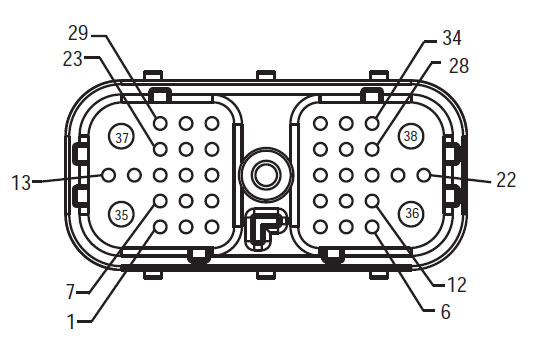
Harness Pogled od spredaj
(HCM – Hibridni sistem Vmesnika)
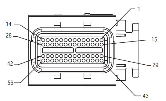
Delphi 56-Way Parjenje priključek Poglej
(inverter – Low Voltage Connector)
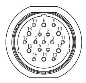
Deutsch 19-Way PEC pas Priključek Poglej
OPOMBA: Nanašajo na Eaton Hybrid komponente in priključek Kraj za lokacije priključkov v MY08 Systems
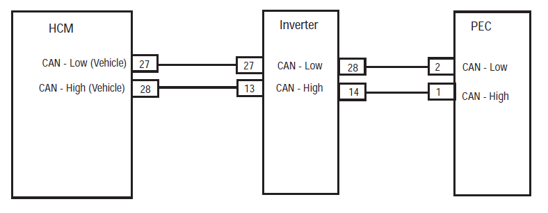
opozorila & Opozorila
nevarnost: Nevarnost pomeni, vas bo hudo poškoduje ali ubije, če ne sledijo naveden postopek.
Opozorilo: Opozorilo označuje takojšnjo nevarnost, ki lahko povzroči hude telesne poškodbe, če ne sledijo naveden postopek.
Opozorilo: Pozor označuje vozilo ali materialno škodo se lahko zgodi, če ne sledijo naveden postopek.
Opomba: Opomba označuje dodatne podrobnosti, da bo pomoč pri diagnozi ali popravilo sestavni del / sistem.
Sledite določene postopke v navedenem vrstnem redu bi preprečili telesne poškodbe:
1. Če so visokonapetostni stožci se okoli vozila in lockout je nameščen na PEC, edina oseba, ki bi moralo biti dovoljeno, da zagon vozila je oseba, ki je podpisala Izpad oznako.
2. Pred delom na vozilu ali izstopu iz kabine, medtem ko motor teče, morate postaviti prestavno ročico v "N" ročno zavoro, in blokirajte kolesa.
3. Iz varnostnih razlogov, vedno sodeluje z delovno zavoro pred izbiro prestav iz "N."
4. Pred začetkom vozilo vedno sedi na voznikovem sedežu, izberite "N" o nadzoru shift, in nastavite parkirne zavore.
5. Pri vozilih z ePTO, motor in / ali
Motor / generator lahko začnete v načinu ePTO. Nikoli kakršnimkoli vzdrževanjem ali delo na vozilu, medtem ko je v tem načinu.
6. 12-Volt baterije pozitivno (+) in negativni (-) mora biti prekinjena pred kakršnimkoli varjenje na vsakem Hybrid opremljena vozila.
Opozorilo: Sledite določene postopke v navedenem vrstnem redu se izognili opreme okvaro ali poškodbo.
Opozorilo: Ne spustite ročno zavoro ali poskus izberite prestavo, dokler zračni tlak je na pravi ravni.
Opozorilo: Da bi se izognili poškodbam prenos med vleko postavite prestavno ročico v "N" in dvignite pogonskih koles od tal ali odklopite pogonski sklop.
High-Voltage Opozorila & Opozorila
- Uporaba CO2 ali suha kemikalija gasilnih aparatov.
- napeljave visoke napetosti je zajeto v oranžno izolacijo ali zviti cevi in označene z opozorilnimi nalepkami na priključke.
- Vse Eaton® Hybrid Diesel / Električna vozila bodo označeni "Hybrid’ na zunanji strani vozila, skupaj z oznako izmene na armaturko.
- Glejte OEM za specifično lokacijo podvozja nameščen hibridnih komponent.
- NE narežemo na oranžno visokonapetostnih kablov.
- NE narežemo na ali odprite PEC.
- NE narežemo na ali odprite DC / DC pretvornik.
- NE narežemo na ali odprite razsmernika.
Varovalni pas mora vzpostaviti in visokonapetostne izolirani gumijaste rokavice (razred 0 z usnjenimi ščitniki) morajo pred delom na visoke napetosti. Neupoštevanje teh navodil lahko povzroči hude telesne poškodbe ali smrt.
Rokavice-gume izolirane, ki jih je treba nositi pri delu na sistemu za visoke napetosti so razred 0 z usnjenimi ščitniki. Gumijaste rokavice, je treba preskusiti pred vsako uporabo po postopku za gume izolacija rokavice testiranje najdemo v "Diagnostična orodja / storitev publikacije" na strani 6. Neupoštevanje teh navodil lahko povzroči hude telesne poškodbe ali smrt.
Pred pregledom ali delajo na vseh visokonapetostnih kablov ali komponente za "High-Voltage storitev zaustavitev in Power-Up postopka" na strani 4 je treba upoštevati. Neupoštevanje teh navodil lahko povzroči hude telesne poškodbe ali smrt.
Naprave Lockout in Tagout je treba odstraniti samo tehnik, ki dajo naprave lockout in Tagout na vozilu. Neupoštevanje teh navodil lahko povzroči hude telesne poškodbe ali smrt.
Visokonapetostne gume izolirane rokavice (razred 0 z usnjenimi ščitniki) je treba nositi pri delu na katerem koli
visokonapetostni kabli. "High-Voltage storitev Shutdown in Power-Up postopek" na strani 4 Upoštevati je treba pred odstranitev katerihkoli visokonapetostnih kablov. Neupoštevanje teh navodil lahko povzroči hude telesne poškodbe ali smrt.
Visokonapetostni kabli in žice so oranžne barve in vsebuje opozorilno oznako na priključke. Visokonapetostne komponente so označene z nalepko. Visokonapetostne gume izolirane rokavice (razred 0 z usnjenimi ščitniki) je treba uporabiti pri delu na kateri koli od teh komponent. Neupoštevanje teh navodil lahko povzroči hude telesne poškodbe ali smrt.
High-Voltage storitev zaustavitev Postopki
 1. Follow "High-Voltage Delovni prostor" postopek.
2. Poiščite rdečo stikalo PEC servisiranje na sprednji PEC in potisnite izklopite.
3. Odstranite Service Switch pokrov in namestite lockout nosilca (J48506).
4. Pritrdite oznaka za lockout Bracket.
5. Zagotoviti Switch PEC storitev ne more premakniti iz položaj za izklop.
6. Pustimo, da se sistem nastavljen za najmanj 5 minut opravljati visoke napetosti.
7. Povežite ServiceRanger in ogled podatkov Monitor PID 116 imenovana "High-Voltage potencial baterije." Uporaba SPN 520323 za priklop J1939 "baterije Napetost RB" (rele Box).
8. Napetost mora biti 30 voltov ali manj. Če je napetost nad 30 voltov, ne delujejo na vozilo in se obrnite Eaton® na 1-800-826-HELP (4357).
9. Obrnite ključ za vžig off in nadaljujte popraviti ali korak težav.
Opomba: Napetost pade na nič, ko je ključ off.
High-Voltage Service Power-up Postopek
1. Namestite vse priključke visokonapetostnih v svoje zaklenjene položajih.
2. Če ste oseba, ki dela na vozilo, odstranite Lockout nosilca in oznako.
3. Ponovno namestite Lockout nosilca preko Switch Service.
4. Potegnite Service Switch ven in pustite niz vozil za 2 minut.
5. Začetek vozilo, če je to primerno.
Eaton Hybrid komponente in priključek Kraj

Eaton Hybrid komponente in priključek Lokacija MY09 sistemi

KORAK 1. Preverite aktivnim in neaktivnim statusom koda napake.
- Pridobivanje Active šifre napak in FMIs z ServiceRanger z uporabo diagnostičnega priključka 9-Way ali ročno.
- Opravite Električni predhodnega preskusa in hibridnimi predpreskus:
- Če ni vprašanj med hibridnimi predpreskus, iti v korak 2.
- Če je problem popraviti v Hybrid elektrotehniko predpreskus, iti v korak 4.
KORAK 2. Preverite kontinuiteto PEC vezij.
- ključ off.
Opozorilo: glejte "High-Voltage storitev Shutdown in postopek Power-Up". Upoštevajte postopke za preprečitev šok, gorijo ali smrt zaradi neustrezno obravnaval visoke napetosti. - Odklopite PEC 19-Way konektor.
- Izmerite upor med PEC 19-Way pinski priključek 1 in Pin 2:
Opomba: Poskrbite, da bo Volt / Ohm Meter je na ustreznem obsegu (okoli 200 ohm lestvica)
Opomba: Nežno upognite razsmernika 56-Way Priključek oprtnik v bližini priključka ob spremljanju vrednosti upora.- Če je upornost med Pin 1 in Pin 2 med 50-70 ohmov, zamenjati za vklop Elektronika Carrier (PEC), potem pa pojdite na korak 4.
- Če upor je izven dosega, iti v korak 3.
KORAK 3. Preverite kontinuiteto med inverterja vezij in PEC vezij.
- Odklopite Inverter 56-Way konektor.
- Izmerite upor med:
- Inverter 56-Way konektor Pin 28 in PEC 19- Way konektor Pin 2
- Inverter 56-Way konektor Pin 14 in PEC 19- Way Connector 1 Opomba: Poskrbite, da bo Volt / Ohm Meter je na ustreznem obsegu (okoli 200 ohm lestvica).
- Če je upornost med Pin 28 in Pin 2 med 0-0,2 ohmov, in upornost med Pin 14 in Pin 1 med 0-0,2 ohmov, zamenjati pretvornika, potem pa pojdite na korak 4.
- Če upor je izven dosega, popravilo CAN Data Link pas med inverterjem in PEC, potem pa pojdite na korak 4.
KORAK 4. Preverite popravilo.
- ključ off.
- Priključite vse priključke in negativni pol akumulatorja.
- Legenda o.
- jasne oznake, glej Jasno Neaktivni Napake.
- Vozite in poskušali ponastaviti kodo.
- Preverite kode, glej Poglej aktivne in neaktivne Napake.
- Če ne kod, Test je končana.
- Če koda napake 89 zdi se, našli napako na testiranju, iti v korak 1.
- Če je koda, razen 89 zdi se, glej Napaka seznam Index koda.
Kaj prenos del morate jo imamo! Isti dan ladijskega prometa na voljo, po vsem svetu.
POTREBUJETE brezplačno podporo našemu strokovnjaku?