Cri Fuller Hybrid Transmission Code Fault 68 – Fault Lichid Grade
Curpa codice di mudelli di sicurezza Drive Eaton Hybrid (MY08) Poste-8E306A-U, EH-8E306A-UPG, Poste-8E306A-UP, EH-8E306A-CD, EH-8E306A-T, Poste-6E606B-CD, (MY09) Poste-8E406A-U / P, Poste-8E406A-UP, Poste-8E406A-UPG, Poste-8E406A-CD, Poste-8E406A-CDG, Poste-8E406A-CDR, Poste-8E406A-T, Poste-6E706B-CD, Poste-6E706B-P è poste-6E706B-UPG. Leghjite sottu per amparà à pruvà, smachjera è comporta errori codice curpa di u vostru Freightliner, Mack, Peterbilt, Kenworth, Institut, International, e camion è usate pisanti-duviri. U Lichid Grade hè una cumpunenti internu di u Module Control Hybrid (HCM). It calculates la scelta veìculu bisognu di u Hill Start assistenti (HSA) funzione à viaghjanu bè. HSA teni timpuraniamenti la Freni Service à ghjochi à permette a cuuperazione òrganu sìngulu-pedi senza u so veìculu massimo daretu.
curpa Code 68 – Détection Fault Lichid Grade
Li siquenti preconditions deve esse scontra nanzu u grippa la curpa:
- Module Control Hybrid (HCM) francese voltage lock hè più cà 7 volts è menu cà 16 volts.
nota: Quandu troubleshooting un codice disarmu qualificà à u Moda Estudiantina prodottu (PDM)
Cundizioni di Piazzà Code Fault Tempo
- veramente 12 s'appronta quandu u filu scelta ùn hè micca Tempo o prisente è HSA hè permessu à i cunfigurazione HCM.
- veramente 13 is set when HSA is enabled in the HCM configuration but the grade sensor has not been calibrated.
- veramente 14 s'appronta quandu u HCM hè dutatu cù una Lichid Grade, HSA hè permessu è lu signali da lu filu hè fora di catena.
Fallback Quandu Code Fault 68 hè stabilitu e condizioni seguenti si verificanu:
- Amber "Vedi Hybrid" illuminated di luce.
- Fault hè cullucatu in Module Control Hybrid (HCM) memoria.
Stu codice curpa si pò causatu da ogni di u dopu:
- veramente 12
- cunfigurazione HCM sgarratu
- HCM
- veramente 13
- calibration Traduzioni Lichid Grade
- cunfigurazione HCM sgarratu
- veramente 14
- HCM
- HCM sgarratu misciu a trasmissioni
curpa Code 68 – Test Fault Lichid Grade
Identificazione Sposa:
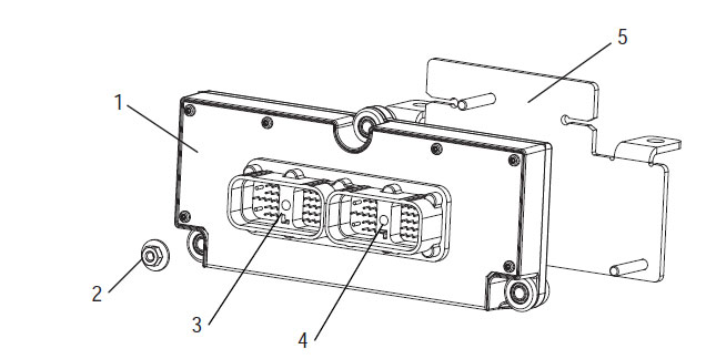
1. Module Control Hybrid (HCM)
2. noce (3)
3. 38-Way System lînia Agnese-in
4. 38-Way Vehicle lînia Agnese-in
5. Plate misciu
DA: Qualificà à u Cri Sposa Hybrid è lînia Location di lînia Locations.
Luna Park & Cautions
piriculu: U periculu indica chì sarete gravemente feriti o uccisi se ùn seguitate micca a procedura indicata.
Attenti: Attenti indica una Translation immediata, chì puderebbe resultà in ferita persunale grave sè ùn seguitate micca a prucedura indicata.
Fate casu: A prudenza indica chì i danni à u veìculu o à a pruprietà ponu accade se ùn seguitate micca a procedura indicata.
nota: Nota indica dettagliu addiziunale chì aiuterà in a diagnosi o riparazione di un componente / sistema.
Piglià u prucedure renseigné in l 'ordine publicata a evitari preghjudiziu vada:
1. Sè i pignotti high-francese voltage sò intornu à u veìculu è i risk hè stallatu à u PEC, u solu parsona chì duvia esse u dirittu à principiatu u so veìculu hè la pirsuna ca firmau l 'tag: risk.
2. Prima di travaglià nant'à un veìculu, o, lassannu lu cabine, mentri lu mutore hè corsa in, tu avissi a postu i to feel passata a "N" crià i spizzò occasion, e bluccà i roti.
3. Per ragioni di sicurità, sempre nu pinzèru u discu serviziu in avanzu à sceltu pusizzioni vigori da "N."
4. Nanzu principianu un veìculu sempre esse assittata a sede di u cunduttore, selezziunà "N" u cuntrollu passata, e misi lu discu occasion.
5. In veìculi cù ePTO, u mutore è / o
Motor / teorija pò principiatu in modu ePTO. Mai guarisce ogni mantene o di u travagliu in u so veìculu, mentri in issu modu di.
6. 12-Eroicu Battery pusitivu (+) è negativa (-) deve esse disconnected avanzu à ogni Saldatura nant'à ogni veìculu Hybrid dutatu.
Fate casu: Piglià u prucedure renseigné in l 'ordine publicata a evitari malfunction vagliatura, o dannu.
Fate casu: Ùn lasciate micca u frenu di staziunamentu nè pruvate à selezziunà un ingranaghju finu à chì a pressione d'aria sia à u livellu currettu.
Fate casu: Per evità danni à a trasmissione durante u rimorchju piazzate a leva di u cambiamentu in "N" è sollevate e rote motrici da a terra o disconnect the driveline.
Luna Park-High francese voltage & Cautions
- Aduprà CO2, o Cavaglieri chimica Fire DISPARURENT.
- U rivets high-francese voltage hè cupartu in mica aranciu o capillaire convoluted è signari incù etichette cunsigliu à i female.
- All Diesel / vehicule Corsu Eaton® Hybrid sarà marcatu 'Hybrid’ u fora di u traspurtadore, rilazione cù u labellu passata nant'à u acquavita.
- Si rifiriscinu a œm per stage specifichi di cumpunenti o châssis muntatu.
- Ùn NOT tagliata in u Francia + high-francese voltage arancia.
- Ùn NOT taglio o apre u PEC.
- Ùn NOT taglio o apre u Convertitore DC / DC.
- Ùn NOT taglio o apre u Inverter.
A zona cuscinettu deve esse stallatu è high-francese voltage ghisa guanti gomma (classi 0 cù prutittura pelle) sò nicissarii in avanzu à u travagliu in u high-francese voltage. Fallimentu di seguità ste instructions, pò risultatu in siveri preghjudiziu vada, o morte.
I guanti gomma-ghisa chì deve esse mìazzu, mentri u travagliu nantu à u sistemu high-francese voltage sò classi 0 cù prutittura pelle. I guanti gomma deve esse pruvatu prima di CULTURE usu seguenti prucedura gomma guanti mica essai trova in "Tools Estudiantina / Service Publications" nant'à pagina 6. Fallimentu di seguità ste instructions, pò risultatu in siveri preghjudiziu vada, o morte.
Nanzu RIAFFACCIASTE o di u travagliu nantu à ogni Francia + high-francese voltage o di cumpunenti di la "-High francese voltage Service bracciale e Power-Up prucidura" nant'à pagina 4 duvia esse seguita. Fallimentu di seguità ste instructions, pò risultatu in siveri preghjudiziu vada, o morte.
U dispusitivi risk è Tagout deve esse cacciatu solu da u BTS chi serbit a dispusitivi risk è Tagout u veìculu. Fallimentu di seguità ste instructions, pò risultatu in siveri preghjudiziu vada, o morte.
gomma ghisa guanti-High francese voltage (classi 0 cù prutittura pelle) deve esse mìazzu quandu u travagliu nantu à ogni
Francia + high-francese voltage. U "Service bracciale-High francese voltage è Power-Up prucidura" nant'à pagina 4 deve esse seguita in avanzu à toglie ogni Francia + high-francese voltage. Fallimentu di seguità ste instructions, pò risultatu in siveri preghjudiziu vada, o morte.
Francia +-High francese voltage è rivets sò aranciu è cuntene un labellu cunsigliu à i female. cumpunenti-High francese voltage sò marcati cù un labellu. gomma ghisa guanti-High francese voltage (classi 0 cù prutittura pelle) deve esse usatu quandu u travagliu nantu à ognuna di sti cumpunenti. Fallimentu di seguità ste instructions, pò risultatu in siveri preghjudiziu vada, o morte.
-High francese voltage prucedure Service bracciale
 1. Follow "Area Work High-francese voltage" prucedura.
2. Piatra lu russu Cambia PEC Service à u fronte di u PEC e fannu passà cumming.
3. Cacciate u Cover Service paese è stallà u braces risk (J48506).
4. tag: guardate a risk braces.
5. Assicurà u paese PEC Service ùn pò muvimentu da a pusizioni cumming.
6. Permettenu di u sistemu di crià di un minimu di 5 minuti à alta alta francese voltage.
7. Cunnette vi ServiceRanger è vede l 'Dumitrache PID Dati 116 chjamata "MEP High-francese voltage Battery." 'Usu SPN 520323 di cunnessione J1939 "Battery francese voltage RB" (Box longa).
8. U francese voltage deve esse 30 volts o menu. Sè u francese voltage hè sopra à 30 volts, ùn travaglià nant'à u veìculu è cuntattu Eaton® à 1-800-826-HELP (4357).
9. Turn key & lock Murat è viaghjà à riparà, o pocu troubleshooting.
nota: U francese voltage gocce à zeru quandu i chiavi hè cumming.
Prucidura High francese voltage-Service Power-Up
1. Stallà tuttu female high-francese voltage in li sô pusizzioni scoppu.
2. S'è tù sì u persona travaglià nant'à u so veìculu, caccià u risk braces è tag:.
3. Stallà i risk braces più di u paese Service.
4. Canapé u Service Cambia fora è ch'elli gruppu veìculu di 2 minuti.
5. Principià veìculu quandu degne.
Cri Sposa Hybrid è lînia Location

Cri Sposa Hybrid è lînia Location MY09 Systems

STEP 1. Verificà FMIs prisente.
- Santa Margherita di u.
- Recuperate i codici di errore attivi è FMI cù ServiceRanger utilizendu u Connettore Diagnosticu 9-Way o manualmente.
- sè FMI 12 hè attivu, vai à Step 2.
- sè FMI 13 hè attivu, vai à Step 3.
- sè FMI 14 hè attivu, vai a mossa 4.
STEP 2. Verificà cunfigurazione HCM.
- Santa Margherita di u.
- Cù ServiceRanger vede u cunfigurazione HCM.
- Sè a cunfigurazione HSA s'appronta à "HSA permessu" e funzione HSA ùn hè bisognu di, selezziunà "No HSA" da u scatula Menu. Salvà stu cambiamentu cunfigurazione da scaricare sceltu, poi vai a Step 5.
- Sè a cunfigurazione HSA s'appronta à "HSA permessu" è hè bisognu funzione HSA, HCM deve esse cambiatu a versione vulcanizing 3.7 o supiriuri cuntenendu una Lichid Grade interna. Cuntattu cri per currettu HCM infurmazione numeru parte.
STEP 3. Verificà Lichid Grade hè calibrate.
- Santa Margherita di u.
- cù ServiceRanger, calibrer u Lichid Grade da sceltu "imágenes Advanced" da u menu principale.
- Selezziunà "Module Control Hybrid."
- Selezziunà "Taratura Lichid Grade" è seguità i instructions, nantu-screnu:
- sè FMI 13 ùn hè micca Tempo dopu calibrating, cumpleta calibration Traduzioni, vai à Step 5.
- sè FMI 13 hè Tempo dopu calibrating, cuntattu papier à 1-800-826-HELP (4357).
STEP 4. Verificà HCM hè û bè.
- Santa Margherita di u.
- Ensure the HCM is properly mounted to the transmission.
- Sè HCM Ùn hè bè muntatu o chioda birrittu sò sciolte, strinciri HCM chioda birritta misciu, poi vai a Step 5.
- Sè HCM hè bè muntatu a trasmissioni, sustituiri HCM. Vede u Module Control Hybrid (HCM) Removal è a prucedura stallanu in TRSM2000, poi jiri a la mossa 5.
STEP 5. verificà riparà.
- off key.
- Reconnect tuttu female è u cavu batterie negativu.
- Santa Margherita di u.
- Selinunte U Populu Và, vede Và Steremu disarmu.
- Caccià u veìculu è tintatu di sviutata u codice.
- Cuntrolla di Selinunte, vede View Steremu Tempo è disarmu.
- Sè ùn Selinunte, testu hè cumpleta.
- Se Code curpa 68 s'affaccia, truvà errore in essai, vai à Step 1.
- Sè un codice tranni 68 s'affaccia, vede Curpa List Code Index.
Any parte trasmissioni tu bisognu di noi sentinu! Corsica Ferries listessu ghjornu disponibile, Borsa.
Bisognu di Support FREE FROM ONE OF nostri sperti?