Eaton Fuller ჰიბრიდული ტრანსმისია ბრალია კოდი 111 – ინვენტორული შეიძლება შეტყობინება ბრალია (HCM)
ბრალია კოდი Eaton ჰიბრიდული წამყვანი სისტემები მოდელები (my08) EH-8E306A-U, EH-8E306A-UPG, EH-8E306A-UP, EH-8E306A-CD, EH-8E306A-T და EH-6E606B-CD. დაწვრილებით ქვემოთ ვისწავლოთ თუ როგორ უნდა შეამოწმოთ, გარკვევა და დაფიქსირება ბრალია კოდი შეცდომები თქვენი Freightliner, Mack, Peterbilt, Kenworth, Volvo, საერთაშორისო, და მძიმე მორიგე სატვირთო და აღჭურვილობა. ინვერტორული ურთიერთობა Battery Control Unit (BCU) მდებარეობს საუბნო საარჩევნო კომისია და ჰიბრიდული კონტროლის მოდული (HCM) შესახებ შეიძლება მაღალი სიჩქარით საკუთრების მონაცემების ლინკი. The data link is a two wire twisted pair with two 120 ohm რეზისტორების მდებარეობს ბმული.
ბრალია კოდი 111 – Inverter ურთიერთობა Detection
შემდეგი წინაპირობები უნდა შეხვდნენ, სანამ სისტემა აღმოაჩენს ბრალია:
- HCM იკვებება და ანთება ძაბვის მეტია, ვიდრე 7 ვოლტი და ნაკლები 16 ვ. ინვერტორული ანთება ძაბვის მეტია, ვიდრე 7 ვოლტი და ნაკლები 16 ვ.
შენიშვნა: როდესაც troubleshooting Inactive კოდი ეხება პროდუქტის დიაგნოსტიკური რეჟიმი (PDM)
პირობები უცნობია ბრალია კოდი აქტიურია)
- საერთაშორისო სავალუტო ფონდის 22 არის, როდესაც Inverter ცნობს შიდა CAN ურთიერთობა მარცხი ძალა up.
- საერთაშორისო სავალუტო ფონდის 23, 24, ან 25 უეჭველია, როდესაც Inverter ვერ გადასცემს, მიიღოს ან მიიღონ ნებისმიერი შეტყობინებები CAN მონაცემთა ლინკები.
- საერთაშორისო სავალუტო ფონდის 26 არის, როდესაც კონკრეტული გაგზავნა გამოგზავნილი HCM არასწორია.
სამარაგო როდესაც ბრალია კოდი 111 არის შემდეგი პირობებით მოხდეს:
- Amber "Check ჰიბრიდი" სინათლის ბზინვარებას.
- ბრალია ინახება ჰიბრიდული კონტროლის მოდული (HCM) მეხსიერება.
- მაღალი ძაბვის Motor / გენერატორი დამხმარე საშუალება ხელმისაწვდომია, მაგრამ შემცირებული თანხა.
პირობები უცნობია ბრალია Code Inactive
მხოლოდ Inactive ხარვეზებით შეიძლება გაირკვეს გადამცემი Electronic Control Unit (TECU) ან ჰიპერტროფიული ისტორიის გამოყენებით ServiceRanger. TECU ავტომატურად აუმჯობესებს ხარვეზებით ისტორიის შემდეგ 200 საათი და HCM ავტომატურად აუმჯობესებს ხარვეზებით ისტორიის შემდეგ ბრალი უკვე უმოქმედო 200 საათი.
ეს ბრალია კოდი შეიძლება გამოწვეული რომელიმე შემდეგი:
- საერთაშორისო სავალუტო ფონდის 22:
- Inverter
- საერთაშორისო სავალუტო ფონდის 23, 24, 25:
- შესაძლებელია მონაცემთა ლინკები
- Inverter
- საუბნო საარჩევნო კომისიის
- საერთაშორისო სავალუტო ფონდის 26
- HCM
- შესაძლებელია მონაცემთა ლინკები
ბრალია კოდი 111 – Inverter ურთიერთობა ტესტი
კომპონენტი საიდენტიფიკაციო my08 სისტემები:
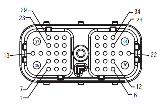
აღკაზმულობა Front View
(HCM – Hybrid System Interface Connector)
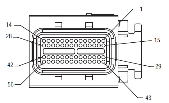
Delphi 56-Way Mating Connector ნახვა
(Inverter დაბალი ძაბვის Connector)
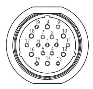
Deutsch 19-Way Mating Connector ნახვა
(საუბნო საარჩევნო კომისიის – დაბალი ძაბვის Connector)
ᲨᲔᲜᲘᲨᲕᲜᲐ: იხილეთ Eaton ჰიბრიდული კომპონენტი და შემაერთებელი მდებარეობა for Connector მისამართები my08 სისტემები
გაფრთხილებები &გამაძლიერებელი; გვაფრთხილებს
Danger: Danger მიუთითებს თქვენ მძიმედ დაშავდა ან დაიღუპა თუ არ მოჰყვება მითითებული პროცედურა.
გაფრთხილება: გაფრთხილება მიუთითებს დაუყოვნებლივ საფრთხის, რომელიც შეიძლება გამოიწვიოს მძიმე დაზიანება, თუ არ დაიცვას აღნიშნული პროცედურა.
Სიფრთხილით: Caution მიუთითებს ავტომობილის ან ქონებრივი ზიანი შეიძლება მოხდეს, თუ არ დაიცვას აღნიშნული პროცედურა.
შენიშვნა: ნოტაში დამატებითი დეტალი, რომელიც დახმარების დიაგნოზი ან შეკეთება კომპონენტი / სისტემა.
დაიცავით მითითებული პროცედურების აღნიშნული, რათა თავიდან ავიცილოთ დაზიანება:
1. იმ შემთხვევაში, თუ მაღალი ძაბვის გირჩები გარშემო მანქანა და ლოკაუტის დამონტაჟებული საუბნო საარჩევნო კომისიის, ერთადერთი ადამიანი, რომ უნდა მიეცეთ დაიწყოს მანქანა არის პირი, რომელმაც ხელი მოაწერა lockout tag.
2. ადრე მომუშავე სატრანსპორტო საშუალება ან ტოვებს კაბინა ძრავა არის გაშვებული, თქვენ უნდა განათავსონ ცვლა ბერკეტი "N" მითითებული პარკირების მუხრუჭი, და დაბლოკოს დისკები.
3. უსაფრთხოების მიზნით, ყოველთვის ჩაერთონ მომსახურება მუხრუჭები ადრე შერჩევის მექანიზმი თანამდებობებზე "ნ"
4. დაწყებამდე მანქანა ყოველთვის უნდა მჯდომარე მძღოლის სავარძლის, აირჩიეთ "N" ცვლა კონტროლი, და მითითებული პარკირების მუხრუჭები.
5. ავტოსატრანსპორტო საშუალებების ePTO, ძრავა და / ან
Motor / გენერატორი შეიძლება დაიწყოს ePTO რეჟიმი. არასოდეს შეასრულოს ნებისმიერი სარემონტო და მუშაობა მანქანა, ხოლო ამ რეჟიმში.
6. 12-Volt Battery დადებითი (+) და უარყოფითი (-) უნდა იყოს გათიშული ადრე ნებისმიერი შედუღების ნებისმიერ Hybrid აღჭურვილია მანქანა.
Სიფრთხილით: დაიცავით მითითებული პროცედურების მითითებულ თავიდან აცილების მიზნით, ტექნიკის malfunction ან დაზიანება.
Სიფრთხილით: არ გაათავისუფლოს პარკირების მუხრუჭი და ცდილობენ შესარჩევად gear სანამ ჰაერის წნევა არის სწორი დონე.
Სიფრთხილით: რათა თავიდან ავიცილოთ დაზიანება გადაცემის დროს საბუქსირე ადგილი ცვლა ბერკეტი "N" და მოხსნის წამყვანი თვლები off ადგილზე ან გაწყვეტა ხაზზე მოძრაობა.
მაღალი ძაბვის გაფრთხილებები & გვაფრთხილებს
- გამოყენება CO2 და მშრალი ქიმიური Fire Extinguishers.
- მაღალი ძაბვის გაყვანილობა არის დაფარული ნარინჯისფერი იზოლაციის ან convoluted მილები და აღნიშნულია გაფრთხილება ეტიკეტები at კონექტორები.
- ყველა Eaton® ჰიბრიდული დიზელი / ელექტრო ტექნიკა იქნება აღნიშნული "ჰიბრიდული’ გარეთ ავტომანქანა, ერთად ცვლა წარწერა dash.
- იხილეთ OEM კონკრეტული ადგილმდებარეობა შასი დამონტაჟებული ჰიბრიდული კომპონენტები.
- არ გაჭრა შევიდა ფორთოხლის მაღალი ძაბვის კაბელები.
- არ გაჭრა ან გახსნას საუბნო საარჩევნო კომისიის.
- არ გაჭრა ან გახსნას DC / DC Converter.
- არ გაჭრა ან გახსნას Inverter.
ბუფერული ზონა უნდა შეიქმნას და მაღალი ძაბვის იზოლირებული რეზინის ხელთათმანები (კლასი 0 ტყავის მფარველები) საჭირო ადრე მუშაობს მაღალი ძაბვის. დაუცველობა დაიცვას ამ ინსტრუქციის შეიძლება გამოიწვიოს მძიმე პირადი დაზიანება ან სიკვდილი.
რეზინის იზოლირებული ხელთათმანები, რომელიც უნდა იყოს ნახმარი მუშაობისას, მაღალი ძაბვის სისტემის კლასის 0 ტყავის მფარველები. რეზინის ხელთათმანები უნდა ტესტირება ყოველი გამოყენების შემდეგ რეზინის იზოლაციის gloves ტესტირება პროცედურა ნაპოვნი "დიაგნოსტიკური ინსტრუმენტები / მომსახურება პუბლიკაციები" გვერდი 6. დაუცველობა დაიცვას ამ ინსტრუქციის შეიძლება გამოიწვიოს მძიმე პირადი დაზიანება ან სიკვდილი.
სანამ შემოწმების ან მუშაობს ნებისმიერი მაღალი ძაბვის კაბელები და კომპონენტები "მაღალი ძაბვის სამსახურის Shutdown და ძალაუფლების პროცედურა" გვერდზე 4 უნდა მოჰყვეს. დაუცველობა დაიცვას ამ ინსტრუქციის შეიძლება გამოიწვიოს მძიმე პირადი დაზიანება ან სიკვდილი.
ლოკაუტის და Tagout მოწყობილობები უნდა იყოს მხოლოდ ამოღებულ მიერ ტექნიკოსი, რომელიც განთავსებული Lockout და Tagout მოწყობილობები მანქანა. დაუცველობა დაიცვას ამ ინსტრუქციის შეიძლება გამოიწვიოს მძიმე პირადი დაზიანება ან სიკვდილი.
მაღალი ძაბვის რეზინის იზოლირებული ხელთათმანები (კლასი 0 ტყავის მფარველები) უნდა იყოს ნახმარი, როდესაც მუშაობა ნებისმიერი
მაღალი ძაბვის კაბელები. The "მაღალი ძაბვის სამსახურის Shutdown და ძალაუფლების პროცედურა" გვერდზე 4 უნდა მოჰყვეს ადრე მოხსნის ნებისმიერი მაღალი ძაბვის კაბელები. დაუცველობა დაიცვას ამ ინსტრუქციის შეიძლება გამოიწვიოს მძიმე პირადი დაზიანება ან სიკვდილი.
მაღალი ძაბვის კაბელები და გაყვანილობა ფორთოხალი და შეიცავდეს გაფრთხილებას ეტიკეტების კონექტორები. მაღალი ძაბვის კომპონენტები აღნიშნულია label. მაღალი ძაბვის რეზინის იზოლირებული ხელთათმანები (კლასი 0 ტყავის მფარველები) უნდა იქნას გამოყენებული, როდესაც მუშაობა რომელიმე ამ კომპონენტების. დაუცველობა დაიცვას ამ ინსტრუქციის შეიძლება გამოიწვიოს მძიმე პირადი დაზიანება ან სიკვდილი.
მაღალი ძაბვის სამსახურის Shutdown პროცედურები
 1. Follow "მაღალი ძაბვის სამუშაო ფართობი" პროცედურა.
2. განთავსდება წითელი საუბნო საარჩევნო კომისიის სამსახურის შეცვლა თვალწინ საუბნო საარჩევნო კომისიის და დააყენებს გათიშვა.
3. ამოღება სამსახურის Switch Cover და დააყენოთ Lockout Bracket (J48506).
4. Fasten tag ლოკაუტის Bracket.
5. დარწმუნდით, რომ საუბნო საარჩევნო კომისიის სამსახურის შეცვლა არ შეუძლიათ გადაადგილება off პოზიცია.
6. საშუალებას სისტემის შექმნას მინიმუმ 5 ე წუთზე განმუხტვა მაღალი ძაბვის.
7. დაკავშირება ServiceRanger და ნახოთ მონაცემები მონიტორი PID 116 ე.წ. "მაღალი ძაბვის ბატარეის პოტენციალი." გამოყენება SPN 520323 for J1939 კავშირი "ბატარეის ძაბვის RB" (relay Box).
8. ძაბვის უნდა იყოს 30 ვოლტი ან ნაკლები. თუ ძაბვის ზემოთ 30 ვ, არ მუშაობს მანქანა და საკონტაქტო Eaton® at 1-800-826 დახმარება (4357).
9. ჩართეთ ანთება გასაღები off და გაგრძელება შეკეთება ან troubleshooting ნაბიჯი.
შენიშვნა: ძაბვის წვეთები ნულის როდესაც გასაღები off.
მაღალი ძაბვის სამსახურის Power-პროცედურა
1. დააინსტალირეთ ყველა მაღალი ძაბვის კონექტორები მათი ჩაკეტილი პოზიციებზე.
2. თუ თქვენ ხართ ადამიანი, მომუშავე მანქანა, ამოიღონ Lockout Bracket და tag.
3. გადააყენეთ Lockout Bracket მეტი სამსახურის შეცვლა.
4. გაიგეთ სამსახურის გადასვლა out და მოდით მანქანა ნაკრები 2 -ე.
5. დაწყება მანქანა, როდესაც შესაბამისი.
Eaton ჰიბრიდული კომპონენტი და შემაერთებელი მდებარეობა

Eaton ჰიბრიდული კომპონენტი და შემაერთებელი საიდან MY09 სისტემები

STEP 1. შეამოწმეთ აქტიური ან არააქტიური ბრალია კოდი სტატუსი და განახორციელოს ელექტრო ტესტის.
- განიხილავს და დაიცვას გაფრთხილებები & გვაფრთხილებს.
- ძირითადი off.
- გასაღები.
- ვიღებ Active ბრალია კოდები და FMIs ერთად ServiceRanger გამოყენებით 9-Way დიაგნოსტიკური Connector ან ხელით.
- ასრულებს ელექტრო ტესტის და ჰიბრიდული ელექტრო ტესტის (ვხედავ "ჰიბრიდი ელექტრო ტესტის" გვერდზე 29):
- თუ არსებობს საკითხები გვხვდება დროს ან ელექტრო ტესტირება, წასვლა ნაბიჯი 2.
- თუ საკითხი გამოცვლილა ან ელექტრო ტესტირება, წასვლა ნაბიჯი 3.
STEP 2. დაადასტურეთ FMIs იმყოფება.
- ძირითადი off.
Danger: აგრეთვე მაღალი ძაბვის სამსახურის ემუქრება და Power პროცედურები. Follow პროცედურები, რათა თავიდან ავიცილოთ შოკი, დამწვრობის ან გარდაცვალების არასწორად სიფრთხილით მაღალი ძაბვის. - რომელიც ხარვეზებით იმყოფებიან?
- თუ ბრალია კოდი 111 საერთაშორისო სავალუტო ფონდის 22 ჩამოთვლილი, შეცვლის Inverter, მერე ნაბიჯი 3.
- თუ ბრალია კოდი 111 საერთაშორისო სავალუტო ფონდის 26 ჩამოთვლილი, საკონტაქტო Eaton® at 1-800-826 დახმარება (4357).
- თუ ბრალია კოდი 111 საერთაშორისო სავალუტო ფონდის 23, 24 ჩამოთვლილია, წადი ბრალია კოდი 88 – შეიძლება ინვენტორული შეტყობინება (HCM)".
- თუ ბრალია კოდი 111 საერთაშორისო სავალუტო ფონდის 25 ჩამოთვლილი აქტიური კოდი 88, წადი ბრალია კოდი 88 – შეიძლება ინვენტორული შეტყობინება (HCM).
- თუ ბრალია კოდი 111 საერთაშორისო სავალუტო ფონდის 25 ჩამოთვლილი აქტიური კოდი 89, წადი ბრალია კოდი 89 – შეიძლება BCU 1 შეტყობინება (HCM).
STEP 3. გადაამოწმოს სარემონტო.
- ძირითადი off.
- ხელახლა ყველა კონექტორები და უარყოფითი ბატარეის კაბელი.
- გასაღები.
- წმინდა კოდები, ვხედავ წმინდა უმოქმედო ხარვეზებით.
- მანქანა მანქანა და ცდილობენ აღადგინოთ კოდი.
- შეამოწმეთ კოდები, ვხედავ ნახეთ აქტიური და არააქტიური ხარვეზებით.
- თუ არ კოდები, ტესტი სრული.
- თუ ბრალია კოდი 11 როგორც ჩანს,, მოვძებნოთ შეცდომა ტესტირება, წასვლა ნაბიჯი 1.
- თუ კოდი გარდა 111 როგორც ჩანს,, ვხედავ ბრალია კოდი ინდექსი სია.
ნებისმიერი გადაცემის ნაწილი თქვენ უნდა, ჩვენ გვაქვს ეს! იმავე დღეს მიწოდება შესაძლებელი, მსოფლიოში.
Need უფასო მხარდაჭერა ერთი ჩვენი ექსპერტები?